Data transmission system, small form factor pluggable transceiver, and method for modifying same

A transmission system and transceiver technology, applied in the field of electronic avionics systems, can solve the problems of not including SFP transceiver welding, expensive, etc.

Active Publication Date: 2020-10-27
THE BOEING CO
View PDF5 Cites 0 Cited by
  • Summary
  • Abstract
  • Description
  • Claims
  • Application Information

AI Technical Summary

Problems solved by technology

The course of action will be expensive
Also, finding a supplier that can manufacture hermetically sealed SFP packages can be challenging, as the hermetic package format is not part of the multisource agreement for SFP transceivers in the fiber optic industry
Existing solutions for partially hardening SFP transceivers involve simply depositing a conformal coating on the SFP transceiver's PCB, but do not include soldering the SFP transceiver to the LRU's PCB

Method used


Image

  • Data transmission system, small form factor pluggable transceiver, and method for modifying same
  • Data transmission system, small form factor pluggable transceiver, and method for modifying same
  • Data transmission system, small form factor pluggable transceiver, and method for modifying same

Examples


Embodiment Construction

[0031] An exemplary embodiment of a method of retrofitting an SFP transceiver to increase its resistance to adverse environmental influences is described in some detail below. However, not all features of an actual implementation are described in this specification. Those skilled in the art will appreciate that in the development of any such actual implementation, numerous implementation-specific decisions must be made to achieve the developer's specific goals, such as system-related and commercial relevant constraints are compatible). In addition, it should be appreciated that such a development effort might be complex and time consuming, but would nevertheless be a routine undertaking for those of ordinary skill in the art having the benefit of this disclosure.

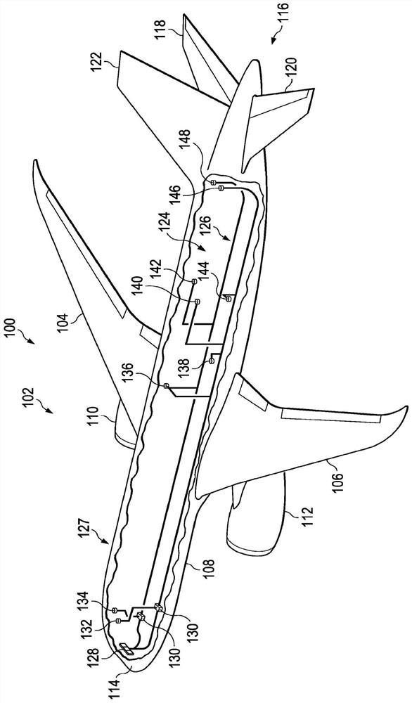
[0032] For purposes of illustration, various embodiments of fiber optic networks for enabling optical communication between field replaceable units on an aircraft are described in detail below. However, the implem...


PUM


Abstract

The disclosure relates to a data transmission system, a small form factor pluggable transceiver, and a method for modifying the same. A method for modifying a low-cost small form factor pluggable optical-electrical bidirectional transceiver (hereinafter "SFP transceiver") by converting the SFP transceiver (2) into a dual-in-line package. Such conversion enables the SFP transceiver (2) to be soldered directly on a printed circuit board (30) of a line replaceable unit of an avionics system, thereby eliminating the concern that the SFP transceiver (2) may become detached due to vibration during aircraft operation. The method also includes a sealing process to protect contact pads (24) on the SFP transceiver (2), thereby eliminating any concern that the contact pads (24) could corrode due to long-term moisture and humidity exposure. The product of the method is a ruggedized SFP transceiver (1) capable of withstanding the rigors of operating in a harsh avionics environment onboard an aircraft (102).

Description

technical field [0001] The technology disclosed herein relates generally to fiber optic networks that enable communication between electrical components. In particular, the technology disclosed herein relates to electronic avionics systems interconnected by an optical avionics data bus. Background technique [0002] For high-speed avionics data networks, the use of fiber optic cables instead of electrical wiring results in significant reductions in weight, cost, electromagnetic effects, and complexity of electrical wiring integration. In modern aircraft, field replaceable units (LRUs), such as avionics computers and sensor units, typically include a housing that houses a transceiver for enabling fiber optic communication with other LRUs. Fiber optic connectors on the LRU housing enable external fiber optic cables to be connected to the LRU. [0003] More specifically, each LRU connected to the optical avionics data bus typically includes an opto-electronic media converter ...

Claims


Application Information

Patent Timeline
Patent Type & Authority Applications(China)
IPC IPC(8): G02B6/42
CPCG02B6/4277G02B6/428G02B6/4274H05K1/117H05K2201/10318H05K2201/09409H05K2203/1572H05K2201/10189H05K2201/10977H05K3/3405H05K2201/10757H05K2201/10568H05K3/3447H05K2201/10121H04B10/40H01R12/57H01R4/023H05K2201/10424H05K2201/1034G02B6/4246H04B10/2589G02B6/2821G02B6/4261G02B6/4278
Inventor E·Y-J·陈D·G·克施恩茨
Owner THE BOEING CO
Why Eureka
Try Eureka