Energy efficiency evaluation method for dynamic reactive power compensation device of power distribution network district

A compensation device and dynamic technology, applied in reactive power compensation, reactive power adjustment/elimination/compensation, circuit devices, etc., can solve problems such as increased power loss and energy loss, lack of energy efficiency evaluation methods, and impact on user power supply quality

Pending Publication Date: 2020-10-27
CHANGSHA UNIVERSITY OF SCIENCE AND TECHNOLOGY
View PDF4 Cites 2 Cited by
  • Summary
  • Abstract
  • Description
  • Claims
  • Application Information

AI Technical Summary

Problems solved by technology

[0002] In the power distribution area, the reasonable allocation of reactive power compensation equipment in the power grid is closely related to the quality of the power supply voltage of the power grid. When the voltage is low, the power loss and energy loss in the system will increase. When the voltage is too low, it will seriously Affect the quality of power supply for users, affect industrial production and residents' lives; when the voltage is too high, the insulation of various electrical equipment may be damaged
Therefore, it is necessary to evaluate the energy efficiency of the dynamic reactive power compensation device in the distribution network station area to achieve a reasonable allocation of reactive power compensation equipment, so that the power quality is guaranteed, the safe operation standard is met, and the requirements of users are met. However, there is currently no effective energy efficiency evaluation. method

Method used


Image

  • Energy efficiency evaluation method for dynamic reactive power compensation device of power distribution network district
  • Energy efficiency evaluation method for dynamic reactive power compensation device of power distribution network district
  • Energy efficiency evaluation method for dynamic reactive power compensation device of power distribution network district

Examples


Embodiment Construction

[0013] The present invention will be further described in detail below in conjunction with the accompanying drawings and specific embodiments.

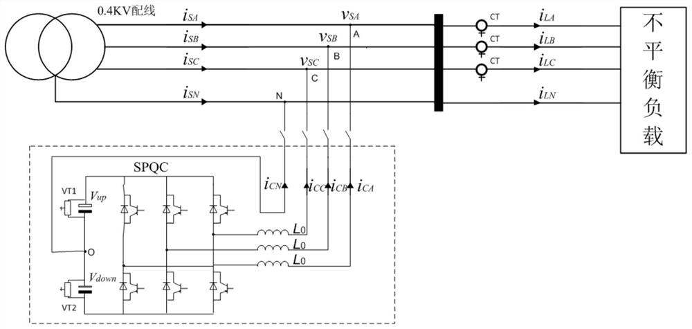
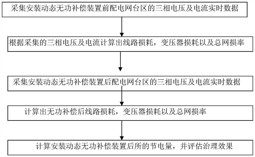
[0014] Such as figure 1 as shown, figure 1 It is the electrical schematic diagram of SVG three-phase unbalance and reactive power compensation, figure 2 A flow chart for the invention. The energy efficiency evaluation method of the dynamic reactive power compensation device in the distribution network station area in the present invention includes the following steps:

[0015] Step 001: Collect real-time data of the three-phase voltage and current of the distribution network station area before installing the dynamic reactive power compensation device; without installing the reactive power compensation device, the three-phase voltage and current of the distribution network station area are in an unbalanced state, and the three-phase The unbalanced current is Ia, Ib, Ic, and the neutral current is In. At this time, the relationship...


PUM


Abstract

The invention discloses an energy efficiency evaluation method for a dynamic reactive power compensation device of a power distribution network district. The evaluation method comprises the followingsteps: acquiring three-phase voltage and current real-time data of the power distribution network district before the dynamic reactive power compensation device is installed; calculating line loss, transformer loss and total network loss rate according to the acquired three-phase voltage and current; collecting three-phase voltage and current real-time data of the power distribution network area after the dynamic reactive power compensation device is installed; calculating line loss, transformer loss and total network loss rate after reactive compensation according to the acquired three-phasevoltage and current; and calculating the power saving amount after the dynamic reactive power compensation device is installed, and evaluating the treatment effect. The method is based on the real-time operation parameters of the power grid, fully considers the loss of the SVG device, can quickly evaluate the energy efficiency of the dynamic reactive power compensation device of the power distribution network district, facilitates the reasonable configuration of reactive power compensation equipment, and guarantees the quality of electric energy.

Description

technical field [0001] The invention relates to an energy efficiency evaluation method of a reactive power compensation device, in particular to an energy efficiency evaluation method of a dynamic reactive power compensation device in a distribution network station area. Background technique [0002] In the power distribution area, the reasonable allocation of reactive power compensation equipment in the power grid is closely related to the quality of the power supply voltage of the power grid. When the voltage is low, the power loss and energy loss in the system will increase. When the voltage is too low, it will seriously It affects the quality of power supply for users, industrial production and residents' lives; when the voltage is too high, the insulation of various electrical equipment may be damaged. Therefore, it is necessary to evaluate the energy efficiency of the dynamic reactive power compensation device in the distribution network station area to achieve a reaso...

Claims


Application Information

Patent Timeline
Patent Type & Authority Applications(China)
IPC IPC(8): H02J3/18H02J3/26G06Q50/06G06Q10/06
CPCH02J3/18H02J3/26G06Q50/06G06Q10/06393H02J2203/20Y02E40/30Y02E40/50Y02E40/70Y04S10/50Y02P90/82
Inventor 陈春彭禹尧曹一家
Owner CHANGSHA UNIVERSITY OF SCIENCE AND TECHNOLOGY
Why Eureka
Try Eureka