Straw recycling system

A technology of straw and recycling box, applied in the application, cutting equipment, agricultural machinery and implements, etc., can solve the problems of uneconomical, affecting the strength of concrete, low bonding force of cementitious materials, etc., to increase frictional resistance and increase bonding force effect

Inactive Publication Date: 2020-10-30
李绍
View PDF1 Cites 3 Cited by
  • Summary
  • Abstract
  • Description
  • Claims
  • Application Information

AI Technical Summary

Problems solved by technology

[0004] In order to make up for the deficiencies of the existing technology and solve the problems that the surface of the straw is smooth, the bonding force with the cementitious material in the concrete is not high, and the excessive diameter of the straw will affect the strength of the concrete and is uneconomical, a straw recycling system proposed by the present invention

Method used


Image

  • Straw recycling system
  • Straw recycling system
  • Straw recycling system

Examples


Embodiment approach

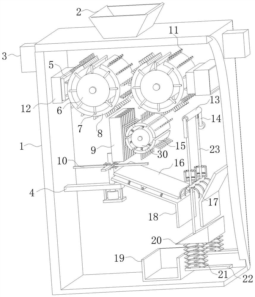
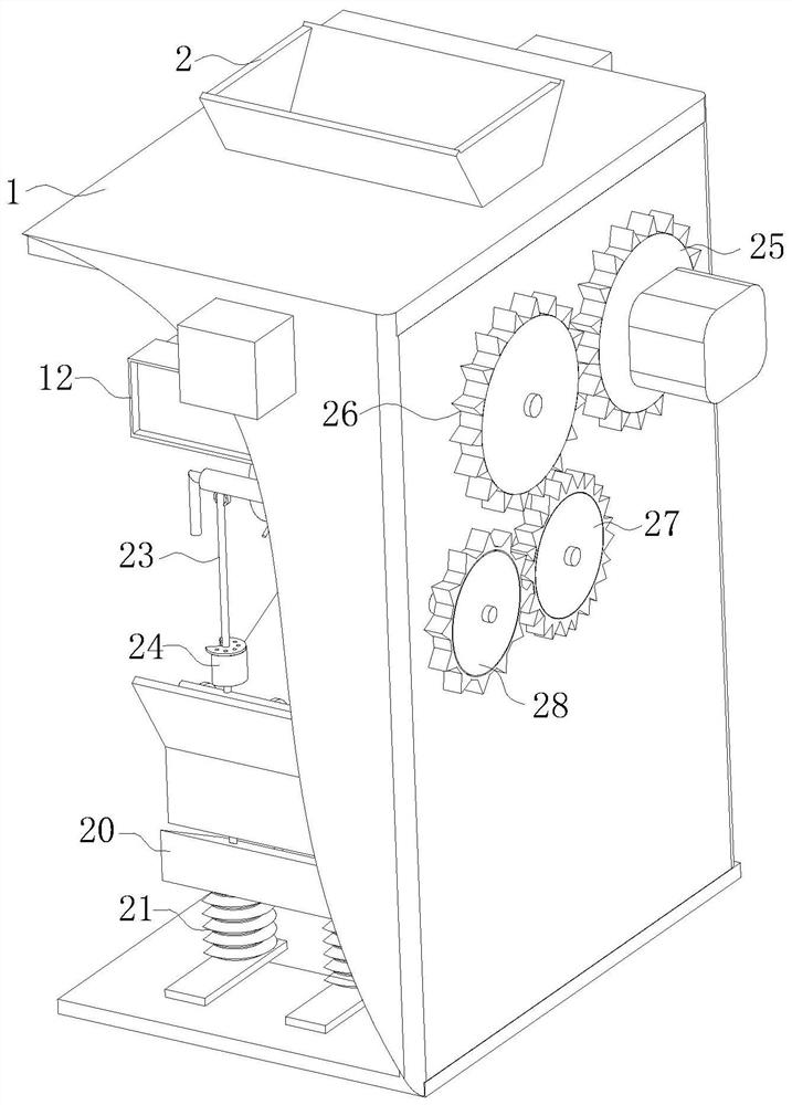
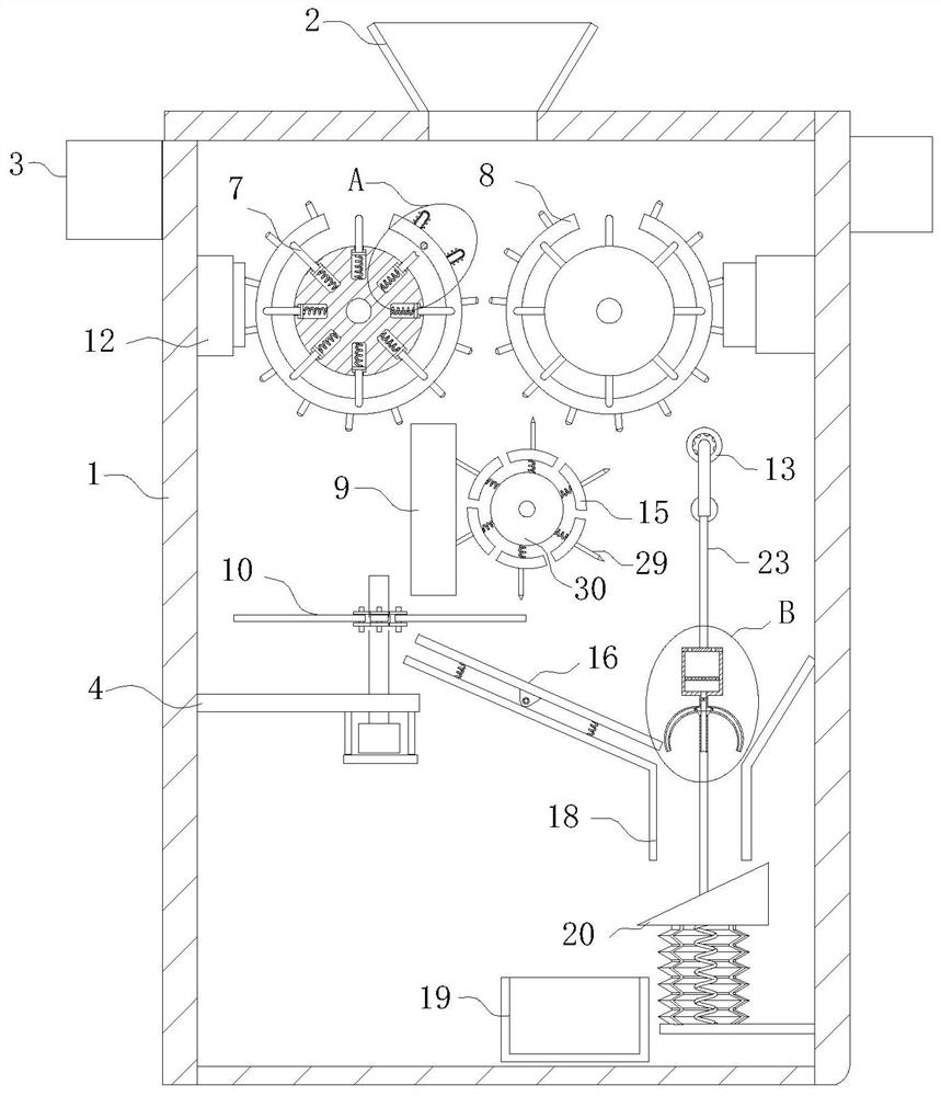
[0029] As an embodiment of the present invention, the acceleration circular gear 27 is meshed with the deceleration circular gear 28 for transmission; the rotating shaft of the deceleration circular gear 28 penetrates the interior of the recovery box 1 and is fixedly connected with one end of the U-shaped rotating rod 14; The U-shaped rotating rod 14 faces the outlet of the discharge chute 18; the horizontal rod of the U-shaped rotating rod 14 is provided with a movable sleeve 13; Fixed connection; the other end of the hollow hose 23 passes through the through hole on the mounting rod 38 and is fixedly connected to the surface of the right mounting plate 22 by a spring; the right mounting plate 22 is fixedly installed on the right side wall of the recovery box 1 The inner wall of the through hole on the described installation rod 38 is fixedly bonded with the outer edge of the hollow hose 23; the left and right sides edges of the described installation rod 38 are fixedly provid...


PUM


Abstract

The present invention belongs to the technical field of straw recycling and particularly relates to a straw recycling system. The straw recycling system comprises a recycling box, a discharge chute and filament splitting needles; a rear side wall of the recycling box is provided with two groups of squeezing rollers and besides the two groups of the squeezing rollers are symmetrically arranged about a bisector of the rear side wall of the recycling box; a rotating shaft of the squeezing roller positioned on a left side penetrates through the rear side wall of the recycling box and is in transmission connection with a driving motor; a driving circular gear is fixedly arranged on a rotating shaft of the driving motor; a rotating shaft of the other group of the squeezing roller penetrates through the rear side wall of the recycling box and is fixedly connected with a driven circular gear; and the driven circular gear and the driving circular gear are in meshed transmission, and a transmission ratio of the driving circular gear to the driven circular gear is one. Straws are subjected to extrusion, filament splitting, roughening, cutting and segmenting, thus the straws are treated into acoarse filament and segment structure which can be better dispersed when applied in cementing materials such as concrete, and besides, the treated straws have good blinding power to the cementing materials and can play functions of enhancing compression resistance and bending resistance of the cementing materials.

Description

technical field [0001] The invention belongs to the technical field of straw recycling, in particular to a straw recycling system. Background technique [0002] Nowadays, all walks of life advocate environmental protection. As a large agricultural country, our country pays more attention to environmental protection; in the past, in rural areas, crop straws were usually not reusable, so most farmers chose to burn them on the spot, which caused great environmental pollution. With the development of society, advocacy In today's environment-friendly environment, there are more and more straw recycling equipment for various crops, but most of the straw recycling equipment currently used is to crush the straw, which can be directly returned to the field after crushing, or used as feed, etc.; such as patent application The patent No. CN201811439094.7 discloses a comprehensive utilization method for crop straw recycling. In this patent, the crop straw is cut by the cutting hob of th...

Claims


Application Information

Patent Timeline
Patent Type & Authority Applications(China)
IPC IPC(8): A01F29/00A01F29/04A01F29/09A01F29/10A01F29/14
CPCA01F29/005A01F29/04A01F29/09A01F29/095A01F29/10A01F29/14
Inventor 李绍李家豪钱威
Owner 李绍
Why Eureka
Try Eureka