Asphalt oil gas treatment system

A technology of oil and gas treatment and asphalt, which is applied in chemical/physical processes, mixers, mixing methods, etc., can solve the problems of inability to guarantee gas compound emission standards, inability to effectively remove oil molecules, and poor human health

Inactive Publication Date: 2020-10-30
梁宗芹
View PDF7 Cites 0 Cited by
  • Summary
  • Abstract
  • Description
  • Claims
  • Application Information

AI Technical Summary

Problems solved by technology

[0002] Asphalt concrete, commonly known as asphalt concrete, is a kind of artificially selected mineral materials with a certain gradation composition, crushed stone or crushed gravel, stone chips or sand, mineral powder, etc., and a certain proportion of road asphalt materials, under strict control The mixture prepared under the conditions, the output and transportation of asphalt concrete, after the asphalt concrete is mixed by the mixer, it is discharged into the transport vehicle, and the transport vehicle transports the concrete to the designated location or the location where the road is paved. However, When the asphalt concrete is discharged from the mixer, and because the mixed asphalt concrete has a certain temperature, it is easy to emit relatively strong asphalt oil gas, which is pungent and harmful to the human body;
[0003] The existing application number is CN201920137694.1, which discloses an asphalt oil and gas treatment system. The asphalt oil and gas enter the pipeline from the air intake device, and then pass through the water treatment device, activated carbon treatment device and plasma treatment device in turn to remove the dust and harmful substances in the asphalt oil and gas. Removed, and then discharged to the external environment through the air outlet device, so as to achieve the purpose of improving the environmental quality of the asphalt concrete production site, but this setting does not specifically treat the oil molecules in the oil and gas, and cannot effectively remove the oil molecules in the oil and gas. The effect is not good. Moreover, after the oil and gas are treated, the treated gas is not detected, and the discharged gas cannot be guaranteed to meet the emission standards, so it is not practical

Method used


Image

  • Asphalt oil gas treatment system
  • Asphalt oil gas treatment system
  • Asphalt oil gas treatment system

Examples


Embodiment Construction

[0027] The following will clearly and completely describe the technical solutions in the embodiments of the present invention with reference to the accompanying drawings in the embodiments of the present invention. Obviously, the described embodiments are only some, not all, embodiments of the present invention. Based on the embodiments of the present invention, all other embodiments obtained by persons of ordinary skill in the art without making creative efforts belong to the protection scope of the present invention.

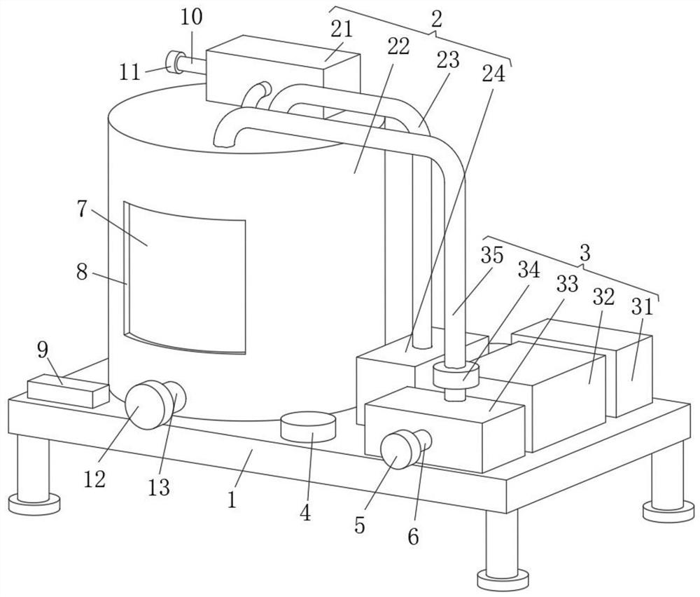
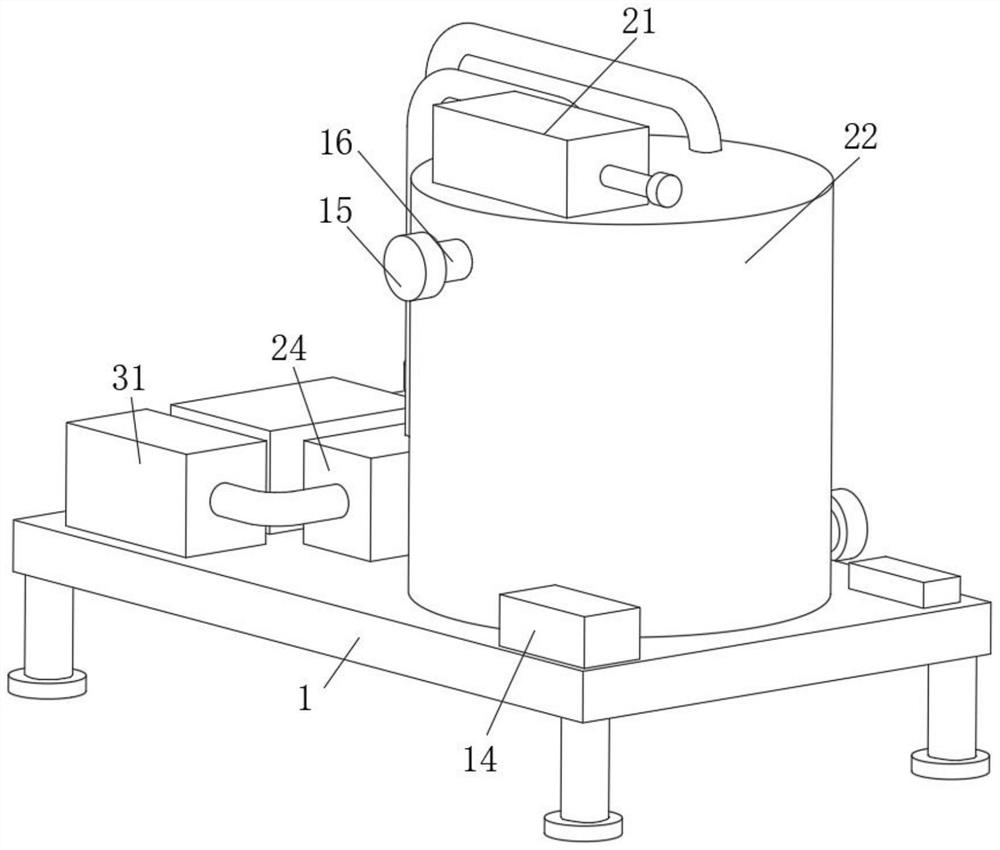
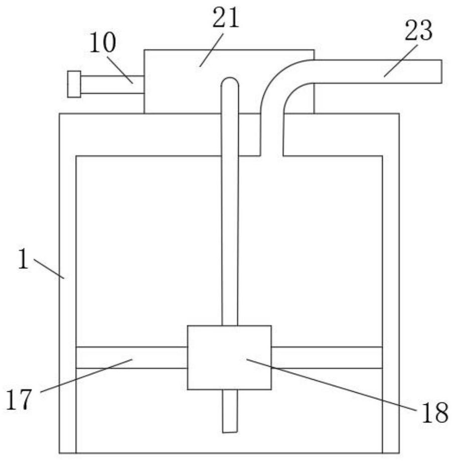
[0028] see Figure 1-3 , the present invention provides a technical solution: an asphalt oil and gas treatment system, including a bottom plate 1, an oil and gas treatment unit 2 and a detection unit 3;

[0029] Bottom plate 1: supports are provided at the four corners of the lower surface, and bases are provided at the lower ends of the supports;

[0030] Oil and gas processing unit 2: it includes a filter box 21, an oil removal tank 22, an air pipe 23 and a...


PUM


Abstract

The invention discloses an asphalt oil gas treatment system. A filter tank is arranged on the upper surface of an oil removal tank; a filter screen is arranged in the filter tank; an air outlet of thefilter tank is communicated with the filter tank through a connecting pipe; an activated carbon box is arranged on the upper surface of the bottom plate; an air outlet of the filter tank is connectedwith an air inlet of the activated carbon box through an air pipe; activated carbon is arranged in the activated carbon box; an xylene solution is arranged in the oil removal tank; one gas outlet ofa three-way joint is communicated with the oil removal tank through a gas return pipe; and an electromagnetic valve is arranged on the gas return pipe. Thereby, oil molecules in oil gas can be specially treated, the oil molecules in the oil gas can be effectively removed, the treatment effect is good, treated gas can be detected, the discharged gas is ensured to meet the emission standard, and practicability is achieved.

Description

technical field [0001] The invention relates to the technical field of waste gas treatment, in particular to an asphalt oil gas treatment system. Background technique [0002] Asphalt concrete, commonly known as asphalt concrete, is a kind of artificially selected mineral materials with a certain gradation composition, crushed stone or crushed gravel, stone chips or sand, mineral powder, etc., and a certain proportion of road asphalt materials, under strict control The mixture prepared under the conditions, the output and transportation of asphalt concrete, after the asphalt concrete is mixed by the mixer, it is discharged into the transport vehicle, and the transport vehicle transports the concrete to the designated location or the location where the road is paved. However, When the asphalt concrete is discharged from the mixer, and because the mixed asphalt concrete has a certain temperature, it is easy to emit relatively strong asphalt oil gas, which is pungent and harmfu...

Claims


Application Information

Patent Timeline
Patent Type & Authority Applications(China)
IPC IPC(8): B01D53/30B01D53/18B01F3/04B01F11/02
CPCB01D53/1487B01D53/1493B01D53/18B01D53/30B01D2252/20B01F23/238B01F31/85
Inventor 梁宗芹
Owner 梁宗芹
Why Eureka
Try Eureka