Mixing equipment for concrete production

A mixing equipment and concrete technology, which is applied to clay preparation equipment, cement mixing equipment, cleaning methods using tools, etc., can solve the problems of prolonging the passing time of concrete, reducing the efficiency of discharging materials, and reducing the efficiency of mixing work, so as to avoid Affect the stirring effect, improve the convenience, and improve the effect of practicability

Inactive Publication Date: 2020-10-30
王小娟
View PDF16 Cites 7 Cited by
  • Summary
  • Abstract
  • Description
  • Claims
  • Application Information

AI Technical Summary

Problems solved by technology

[0003] After the existing concrete mixer piece completes the mixing work, after the concrete is discharged, a large amount of concrete is easily solidified on the inner wall of the main body, resulting in a reduction in the volume of the main body, thereby reducing the amount of concrete that can be mixed, thereby reducing the working efficiency of mixing Not only that, when the existing concrete mixer is discharging, it usually discharges the outside of the main body through the gravity of the concrete itself, but due to the certain viscosity of the concrete, the speed of the concrete passing through the discharge pipe is slowed down, thereby prolonging the passing time of the concrete. time, reducing the work efficiency of nesting, thus greatly reducing the practicability of existing concrete

Method used


Image

  • Mixing equipment for concrete production
  • Mixing equipment for concrete production
  • Mixing equipment for concrete production

Examples


Embodiment Construction

[0026] The present invention is described in further detail now in conjunction with accompanying drawing. These drawings are all simplified schematic diagrams, which only illustrate the basic structure of the present invention in a schematic manner, so they only show the configurations related to the present invention.

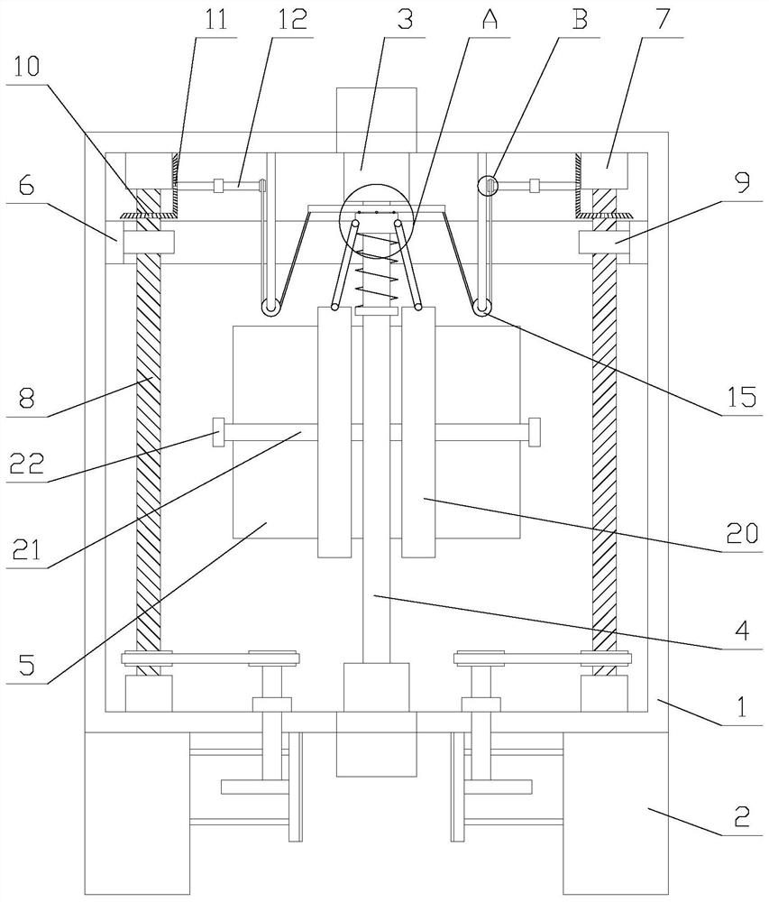
[0027] Such as figure 1 As shown, a mixing device for concrete production includes a main body 1, a first motor 3, a first bearing, a stirring shaft 4, two stirring plates 5 and two support blocks 2, and the two support blocks 2 are respectively fixed on On both sides of the lower part of the main body 1, a feed pipe and a discharge pipe are respectively arranged above and below the main body 1, and the first motor 3 and the first bearing are respectively fixed on the top and bottom of the main body 1. The first motor 3 is connected in transmission with one end of the stirring shaft 4, and the other end of the stirring shaft 4 is fixedly connected with the in...


PUM


Abstract

The invention relates to mixing equipment for concrete production. The mixing equipment for concrete production comprises a main body, a first motor, a first bearing, a stirring shaft, two stirring plates and two supporting blocks, and further comprises a cleaning mechanism and two vibrating mechanisms. The cleaning mechanism comprises a scraping plate, fixed plates, springs, a connecting block, aconnecting plate, two cleaning assemblies, two lifting assemblies and two driving assemblies. Each cleaning assembly comprises a cleaning plate and a hinge bar. Each vibrating mechanism comprises a transmission assembly, a rotary shaft, a second bearing, an eccentric wheel, a knocking plate and a plurality of elastic ropes. The mixing equipment for concrete production can clean the inner wall ofthe main body through the cleaning mechanism, prevents much concrete from solidifying on the inner wall of the main body and reducing the volume of the main body, thereby having no influence on the stirring effect. The mixing equipment achieves the function of knocking a discharge pipe through the vibrating mechanisms, vibrates concrete by vibrating the discharge pipe, thereby increasing the speedof the concrete passing through the discharge pipe, improving the discharge efficiency and reducing the blockage probability of the discharge pipe.

Description

technical field [0001] The invention relates to the field of construction engineering, in particular to a mixing device for concrete production. Background technique [0002] Concrete mixer is a machine that mixes cement, sand and gravel aggregate and water and mixes it into concrete mixture, and the concrete mixing blade is a part installed on the concrete mixer. By turning the driving device on the concrete mixer, the concrete mixing blade is The concrete mixer rotates circumferentially, so that the concrete is fully mixed in the concrete mixer. [0003] After the existing concrete mixer piece completes the mixing work, after the concrete is discharged, a large amount of concrete is easily solidified on the inner wall of the main body, resulting in a reduction in the volume of the main body, thereby reducing the amount of concrete that can be mixed, thereby reducing the working efficiency of mixing Not only that, when the existing concrete mixer is discharging, it usually...

Claims


Application Information

Patent Timeline
IPC IPC(8): B28C5/08B28C5/16B28C7/16B08B1/00
CPCB28C5/0806B28C5/16B28C7/162B08B1/165
Inventor 王小娟
Owner 王小娟
Why Eureka
Try Eureka