Drain system for blast furnace hearth standing water

A drainage system and blast furnace technology, applied in the blast furnace field, can solve the problems of not considering the pipeline cleaning measures, affecting the drainage effect of the blast furnace hearth, and complicated drainage pipeline layout, etc., and achieve the effect of simple composition, reduced impact, and convenient maintenance

Pending Publication Date: 2020-10-30
CISDI ENG CO LTD +2
View PDF1 Cites 4 Cited by
  • Summary
  • Abstract
  • Description
  • Claims
  • Application Information

AI Technical Summary

Problems solved by technology

In the patented scheme, the drainage pipelines are arranged in series and interlaced with each other. Although the accumulated water in the furnace can be collected to the largest extent, the layout of the drainage pipelines is complicated, and it is difficult to implement in actual production. In addition, the solution does not consider the cleaning measures after the pipeline is blocked, maintenance Inconvenient, once the pipeline is blocked, the entire drainage pipeline may not be able to discharge water, which will affect the drainage effect of the blast furnace hearth

Method used


Image

  • Drain system for blast furnace hearth standing water
  • Drain system for blast furnace hearth standing water
  • Drain system for blast furnace hearth standing water

Examples


Embodiment 1

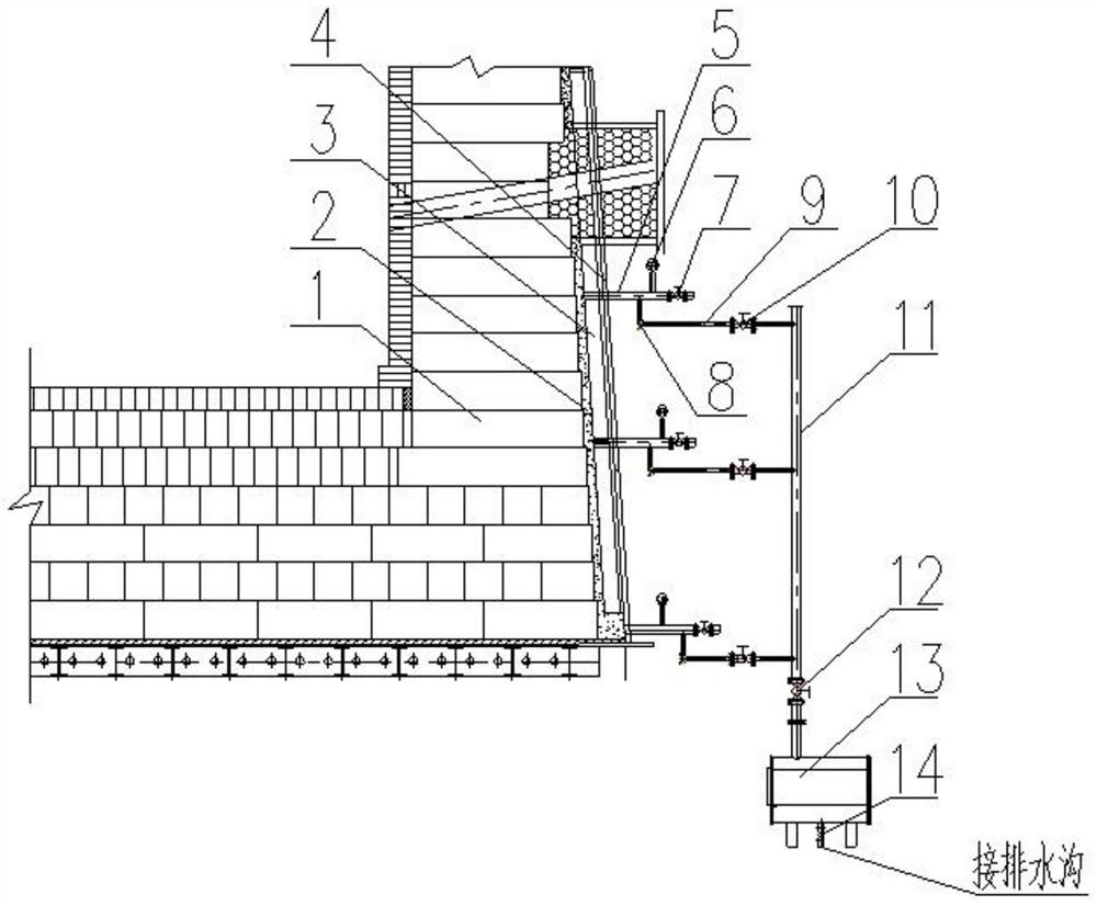
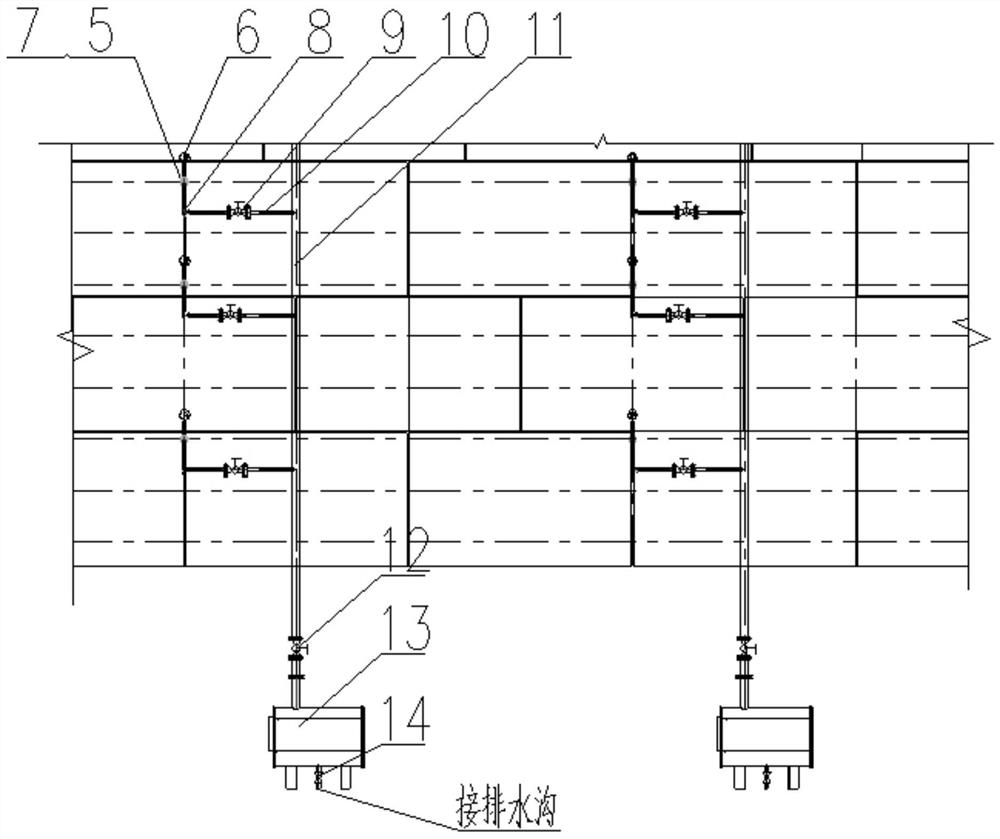
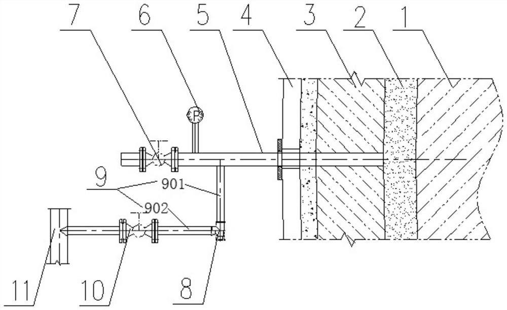
[0048] Such as Figure 1 to Figure 3 , Figure 5 as well as Figure 8 As shown, the water inlet end of the short drainage pipe 5 is shared with other orifices, and extends into the hearth of the blast furnace to collect accumulated water in the blast furnace furnace. Other orifices can be thermocouple holes, or grouting holes or reserved holes, etc., if When there is no available hole on the wall of the blast furnace, the short drain pipe 5 is directly drilled into the wall of the blast furnace. When the short drainage pipe 5 shares the orifice with the grouting hole or the reserved hole, the cooling equipment 3 provided on the cold surface of the joint filler 2 is a cooling wall, and the outer side of the cooling wall is a furnace shell 4 made of steel plate, and the short drainage pipe 5 is sequentially Pass through the furnace shell 4, the cooling equipment 3, and the joint filler 2 to extend into the refractory brick 1, and the outer end of the short drainage pipe 5 is f...

Embodiment 2

[0050] Such as figure 1 , figure 2 , Figure 4 , Figure 6 to Figure 8 As shown, the water inlet end of the short drainage pipe 5 passes through the furnace wall of the blast furnace to collect accumulated water in the blast furnace. During installation, it is also possible to use the fixing bolt holes of the cooling device 3 to set a drainage pipeline to discharge the accumulated water in the furnace hearth. . Generally, the cooling equipment 3 is fixed to the furnace shell 4 with 4 solid bolts 19, and 1 to 2 of the solid bolts 19 can be replaced with hollow bolts 18 under the premise of ensuring safety, and the short drain pipe 5 and the fixing bolts of the cooling equipment 3 The holes are shared. After the cooling equipment 3 is installed, holes are drilled on the bolt hole sealing cover 17. The short drain pipe 5 passes through the bolt hole sealing cover 17 and is connected with the hollow bolt 18, so that the accumulated water in the furnace hearth can be directly d...


PUM


Abstract

The invention relates to a drain system for blast furnace hearth standing water, and belongs to the field of blast furnaces. The drain system comprises short drain pipes, branch drain pipes and a maindrain pipe. The tail end of the main drain pipe is connected with an automatic drain device. Pressure detection devices and overhaul valves are arranged on the short drain pipes. The overhaul valvesare arranged at the positions, behind the pressure detection devices, of the tail ends of the short drain pipes. The branch drain pipes comprise straight pipe sections I and straight pipe sections II.One ends of the straight pipe sections I are connected with one ends of the straight pipe sections II through overhaul three-way valves to form L-shaped pipe body structures, the other ends of the straight pipe sections are connected to the short drain pipes, and the other ends of the straight pipe sections II are connected to the main drain pipe. The whole drain pipeline composition is simple, the standing water gathered in furnace hearths in the production process of the blast furnaces can be drained in time, online unblocking can be achieved, maintenance is convenient, the service life ofthe blast furnace hearths is prolonged, and economic benefits are increased.

Description

technical field [0001] The invention belongs to the field of blast furnaces, and in particular relates to a drainage system for accumulated water in a hearth of a blast furnace. Background technique [0002] Blast furnace ironmaking is the main process of ironmaking technology. In recent years, blast furnaces at home and abroad have frequently suffered hearth burn-through accidents and suffered from abnormal temperature rises in hearth carbon bricks. Burn-through, the production life of the blast furnace is greatly reduced, which seriously threatens the safe production of the blast furnace and causes huge economic losses to the enterprise. The long-term stable operation of the blast furnace hearth mainly depends on the stable heat transfer system formed by the cooling equipment and refractory materials. However, in the actual production process, there will be air gaps between the cooling equipment and the refractory materials due to problems such as water leakage and gas flo...

Claims


Application Information

Patent Timeline
Patent Type & Authority Applications(China)
IPC IPC(8): C21B7/14C21B7/24
CPCC21B7/14C21B7/24
Inventor 赵运建邹忠平徐灿肖学文王刚张玉栋许俊牛群李杰
Owner CISDI ENG CO LTD
Why Eureka
Try Eureka