
Deformation type outward convex transition stepped energy dissipation structure and energy dissipation method thereof

A ladder, energy dissipation technology, applied in water conservancy engineering, marine engineering, coastline protection and other directions, can solve the problems of large negative pressure, large negative pressure on the dam surface, insufficient air aeration on the overflow dam surface, etc.

Inactive Publication Date: 2020-10-30
KUNMING UNIV OF SCI & TECH
View PDF2 Cites 0 Cited by
  • Summary
  • Abstract
  • Description
  • Claims
  • Application Information

AI Technical Summary

Problems solved by technology

Due to the unreasonable design of the discharge structure and the poor structural design of the connection between the WES surface and the stepped overflow dam, the discharge water flow cannot pass through the transition section smoothly, resulting in insufficient air entrainment on the overflow dam surface and localized dam surface. Larger negative pressure, resulting in cavitation cavitation damage
The current solutions are: the dam surface generates a large local negative pressure, resulting in cavitation cavitation damage

Method used


Image

  • Deformation type outward convex transition stepped energy dissipation structure and energy dissipation method thereof
  • Deformation type outward convex transition stepped energy dissipation structure and energy dissipation method thereof
  • Deformation type outward convex transition stepped energy dissipation structure and energy dissipation method thereof

Examples


Embodiment 1

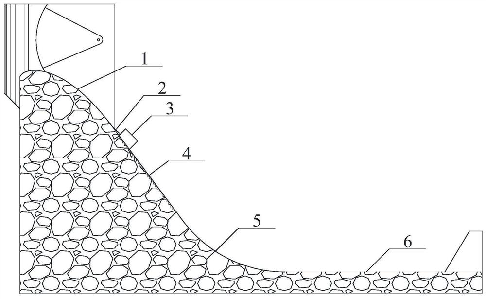
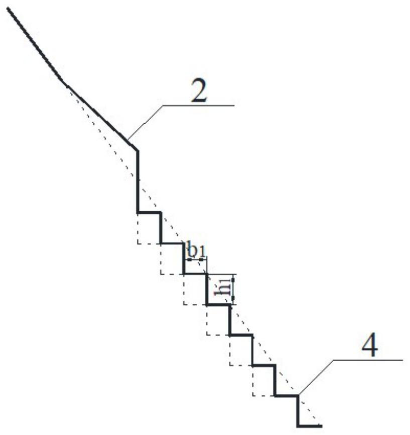
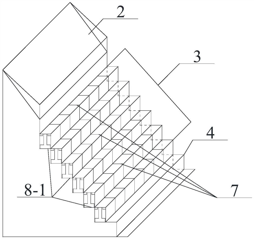
[0038] Embodiment 1: as Figure 1-14As shown, a modified form of convex transitional ladder energy dissipation structure, the modified form of convex transitional ladder energy dissipation structure is set on the middle step straight line section of the overflow dam, the overflow dam includes WES curve section 1, the middle Step straight section, reverse arc section 5, and stilling pool section 6; WES curve section 1 is connected to the intermediate ladder straight section, the middle ladder straight section is connected to reverse arc section 5, and reverse arc section 5 is connected to stilling pool section 6; The modified outwardly convex transitional stepped energy dissipation structure includes a front aeration sill 2, an outwardly convex transitional step section 3, a uniform stepped section 4, a unit block 7, a hydraulic jacking device 8-1, and a controller; From the high position to the low position of the overflow dam, the modified outwardly convex transitional steppe...

Embodiment 2

[0043] Embodiment 2: as Figure 1-14 As shown, a modified outwardly convex transitional ladder energy dissipation structure and energy dissipation method, this embodiment is the same as Embodiment 1, the difference lies in: the hydraulic jacking device at the bottom of several unit blocks 7 in the same row 8-1 Encapsulate through the shell, and use the shell as the unit block 7 in the jacking state when the unit block 7 is lifted away from the facade at the height of the large step (that is, in the form of Figure 5 As an example, h2 at this time represents the initial height of the unit block 7, plus the height of the unit block being jacked up, the height refers to the elevation, and when the unit block is jacked up, the elevation of the unit block The bottom surface forms an opening with the level of the large step, which opening is supplemented by the housing of the hydraulic jacking device 8-1.

Embodiment 3

[0044] Embodiment 3: A modified outwardly convex transitional ladder energy dissipation structure and energy dissipation method. This embodiment is the same as Embodiment 1, the difference is that in this embodiment, the Ahai Hai Hydropower Station is used as the prototype to carry out numerical simulation calculation research , once in 5000 years (17500m 3 / s) flood level and once in 1000 years (15300m 3 / s) to measure the distribution of negative pressure on the stepped overflow surface of the Ahai Sea Hydropower Station. At this time, the structural size design of the transitional step of the model is as follows: figure 2 , image 3 As shown, the first 6 steps are uniform steps, the step height h1 of the uniform step section 4 is 1.0m, and the width b1 is 0.75m. The slope of the entire ladder section is 1:0.75, the radius of the anti-arc surface is 50m, and the length of the downstream stilling pool is 155.59m.

[0045] The structural design of the transitional steps o...


PUM

PropertyMeasurementUnit
Widthaaaaaaaaaa

Abstract

The invention relates to a deformation type outward convex transition stepped energy dissipation structure and an energy dissipation method thereof. The structure comprises a front aerator, an outwardconvex transition stepped segment, a uniform stepped segment, unit blocks, hydraulic jacking devices and a controller. The front aerator, the outward convex transition stepped segment and the uniformstepped segment are sequentially arranged from the high position to the low position of an overflow dam. The outward convex transition stepped segment is uniformly divided into the multiple unit blocks, the corresponding hydraulic jacking device is mounted on the lower portion of each unit block, all the hydraulic jacking devices are controlled by a control system in a unified manner through control circuits, and the control system is used for controlling the hydraulic jacking units to drive the unit blocks to ascend and descend so as to adjust the stepped height of the outward convex transition stepped segment. According to the structure, under the action of the front aerator and the outward convex transition stepped segment, the aeration energy dissipation effect of water flow is increased to some extent, dam body safety of a flood releasing structure under different kinds of single width flow can be effectively protected, and cavitation and cavitation erosion of the overflow dam can be avoided.

Description

technical field [0001] The invention relates to a modified outwardly convex transitional ladder energy dissipation structure and an energy dissipation method thereof, belonging to the technical field of energy dissipation for stepped overflow dams of water conservancy and hydropower. Background technique [0002] A large number of experimental studies and engineering practices at home and abroad have shown that when the water flow velocity across the dam is high, the cavitation resistance can be improved by enhancing the strength of the flow wall material and controlling the unevenness. Not only the project cost is high, but also often The purpose of preventing cavitation cannot be achieved, and adding aerated corrosion reduction facilities is an economical and effective measure. Spillway design code stipulates that air-entrainment measures should be taken for discharge structures with a flow velocity greater than 30m / s. Due to the unreasonable design of the discharge struc...

Claims


Application Information

Patent Timeline
IPC IPC(8): E02B8/06E02B8/00
CPCE02B8/06E02B8/00
Inventor 牛安琪任中成池晓清邱毅陈卫星张晓霞
Owner KUNMING UNIV OF SCI & TECH
Learn More