Non-contact current sensor and using method thereof

A current sensor, non-contact technology, applied in the field of sensors, can solve the problems of high material cost, low measurement accuracy, complex processing technology, etc., and achieve the effect of strong environmental adaptability, high level of intelligence, and quick disassembly and replacement

Pending Publication Date: 2020-10-30
国创时代(北京)地磁导航通信技术有限公司
View PDF0 Cites 4 Cited by
  • Summary
  • Abstract
  • Description
  • Claims
  • Application Information

AI Technical Summary

Problems solved by technology

[0017] The open-loop Hall current sensor is mainly used to measure various currents from 0 to 100KHz. The measurement accuracy is generally ±1%, the nonlinearity is 0.5%, the response speed is 10μs, and the tracking speed is 50A / μs. The structure of the sensor is simple, but it is greatly affected by temperature, the measurement accuracy is low, the response time is not fast enough, the frequency bandwidth is narrow, and the residual magnetism in the optimal magnetic circuit has a greater impact on the measurement accuracy
The closed-loop Hall current sensor is characterized by high precision, fast response, and wide frequency band, but it also has defects such as poor overload capacity, large volume, complicated process, and high price.
[0018] It can be seen that whether it is an open loop or a closed loop, the Hall current sensor needs a magnetic gathering ring when it is in use, and the measured object is placed in the magnetic gathering ring. The magnetic gathering ring is on the annular high magnetic permeability rod It is made of enameled wire wound with multi-turn coils, the material cost is high, and the processing technology is complicated. In addition, in many measurement applications, it is not allowed or inconvenient to install the magnetic ring, which brings a lot of trouble to the measurement.

Method used


Image

  • Non-contact current sensor and using method thereof
  • Non-contact current sensor and using method thereof
  • Non-contact current sensor and using method thereof

Examples


Embodiment Construction

[0046] The technical solutions in the embodiments of the present application are clearly and completely described below in combination with the drawings in the embodiments of the present application. Obviously, the described embodiments are part of the embodiments of the present application, not all of them. Based on the embodiments in this application, all other embodiments obtained by those skilled in the art without making creative efforts belong to the scope of protection of this application.

[0047] The application provides a non-contact current sensor, including a GMI sensor and a shield;

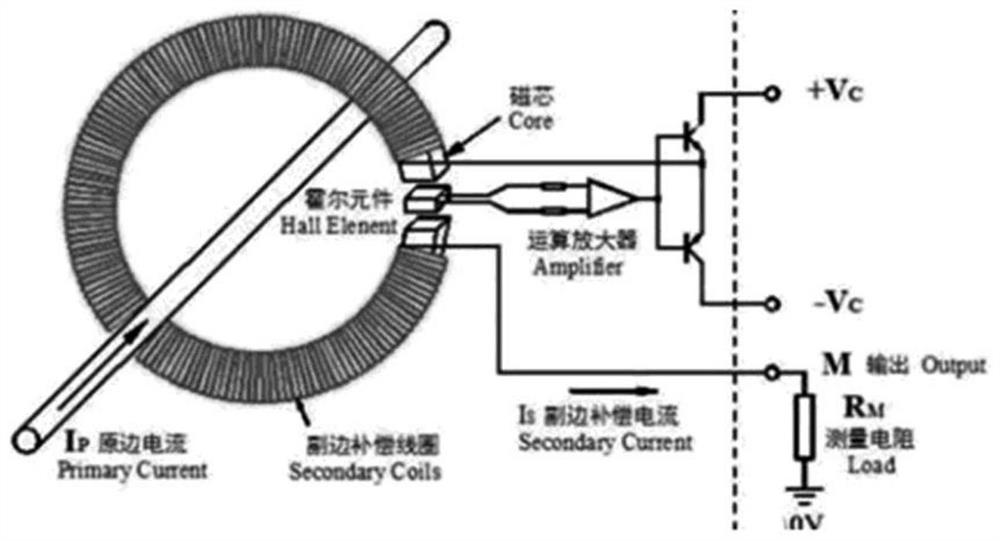
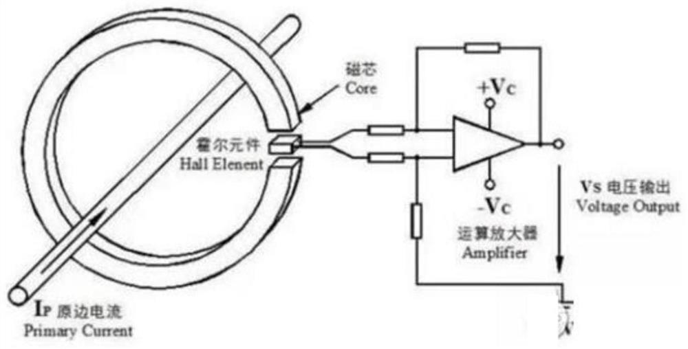
[0048] The GMI magnetic sensor 1 has a probe 11, and the probe includes an amorphous wire and a detection coil. When the measured cable or conductor passes a current, according to Ampere's law, a magnetic field proportional to the current will be generated around the current-carrying conductor, The probe of the GMI magnetic sensor can detect the magnetic field strength in real time; ...


PUM

PropertyMeasurementUnit
thicknessaaaaaaaaaa
thicknessaaaaaaaaaa

Abstract

The invention provides a non-contact current sensor. The non-contact current sensor comprises a GMI magnetic sensor, a shielding body, a circuit processing module and a single-chip microcomputer, theGMI magnetic sensor and the circuit processing module are electrically connected with the single-chip microcomputer. The GMI magnetic sensor is provided with a probe, the probe can detect magnetic field information generated by a detected object, and the circuit processing module and the single-chip microcomputer can convert the magnetic field information into detection values. The probe is arranged in the shielding body, and the shielding body is a metal box body with a certain thickness and high magnetic conductivity. The invention further provides a using method of the non-contact current sensor, and the method comprises the steps: obtaining the shielding body meeting the requirements according to the maximum value of the magnetic field intensity which can be generated by the to-be-measured object; arranging a probe of the GMI magnetic sensor in the shielding body; placing the non-contact current sensor beside an object to be measured; and electrifying the non-contact current sensorto obtain a detection value of the to-be-detected object. The current detection efficiency is improved.

Description

technical field [0001] The present application belongs to the technical field of sensors, and in particular refers to a non-contact current sensor and a method for using the same. Background technique [0002] Driven by the development and upgrading of my country's industry, the safe use of power equipment has received more and more attention. As a tool with both protection and monitoring functions, current sensors will play an increasingly important role in power grid operation management and electromechanical equipment control now and even in the future. Compared with similar foreign products, there is still a big gap in domestic current sensor technology that needs to be made up and improved. [0003] With the development of smart grid technology at home and abroad and the continuous improvement of safety requirements for electromechanical equipment, the requirements for current sensor measurement accuracy, stability, reliability, intelligence level and online non-contac...

Claims


Application Information

Patent Timeline
Patent Type & Authority Applications(China)
IPC IPC(8): G01R15/14
CPCG01R15/148
Inventor 刘景毅钱阳李燕南高秀卫李定朋高新春
Owner 国创时代(北京)地磁导航通信技术有限公司
Why Eureka
Try Eureka