
High-temperature self-extinguishing power distribution cabinet

A power distribution cabinet, high temperature technology, applied in the field of high temperature self-extinguishing power distribution cabinet, can solve the problems of small heat dissipation holes, insufficient combustion and insufficient oxygen in the power distribution cabinet

Active Publication Date: 2020-10-30
圣道天德电气(山东)有限公司
View PDF7 Cites 6 Cited by
  • Summary
  • Abstract
  • Description
  • Claims
  • Application Information

AI Technical Summary

Problems solved by technology

[0003] In hot weather, the heat generated by the electronic components in the power distribution cabinet cannot be dissipated in time, which makes it easy to cause fire in the power distribution cabinet, which is easy to cause property loss. In addition, the current power distribution cabinet is designed to prevent The effect of rain and dust prevention makes the heat dissipation holes on the power distribution cabinet smaller, and when a fire occurs in the power distribution cabinet, there will be insufficient oxygen and insufficient combustion, which will cause a large amount of carbon monoxide to be generated in the power distribution cabinet. When the cabinet door is opened to extinguish the fire of the power distribution cabinet, a large amount of carbon monoxide will be sprayed out. Because carbon monoxide has certain toxicity, it will endanger the health of the staff.

Method used


Image

  • High-temperature self-extinguishing power distribution cabinet
  • High-temperature self-extinguishing power distribution cabinet
  • High-temperature self-extinguishing power distribution cabinet

Examples


Embodiment 1

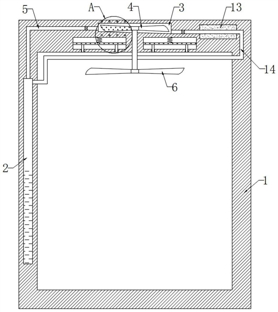
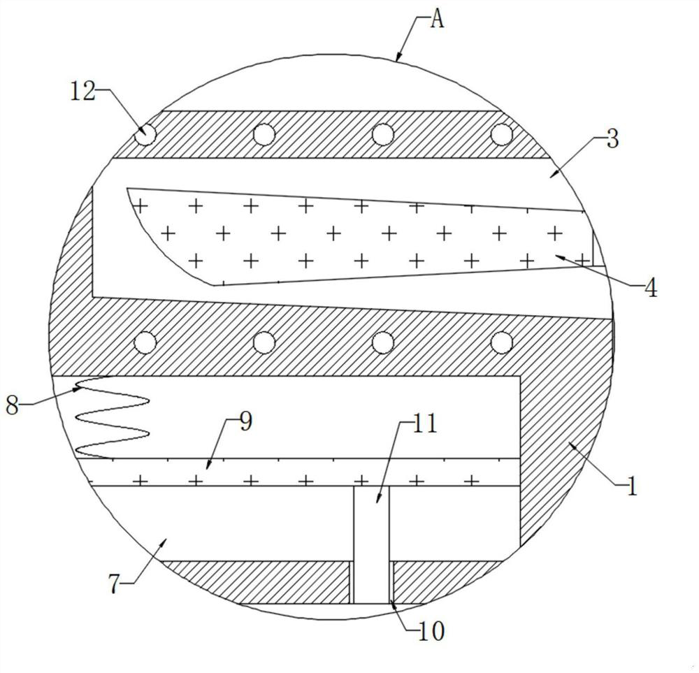
[0024] refer to Figure 1-2 , a high-temperature self-extinguishing type power distribution cabinet, including a cabinet body 1, a liquid storage chamber 2 is opened on the side wall of the cabinet body 1, and the liquid storage chamber 2 is filled with evaporating liquid, further, the evaporating liquid is an aqueous solution, and the upper end of the cabinet body 1 There is a circular cavity 3, and the bottom of the circular cavity 3 is connected with a plurality of impellers 4 through the rotating shaft. There is a pressure relief valve, and the mouth of the one-way air inlet pipe 5 is inclined to the direction of the multiple impellers 4. It should be noted that the one-way air inlet pipe 5 only allows gas to enter the circular chamber 3 from the liquid storage chamber 2. When the cabinet body 1 When a fire breaks out and the evaporative liquid evaporates rapidly, the pressure in the liquid storage chamber 2 reaches the critical value of the pressure relief valve, so that ...

Embodiment 2

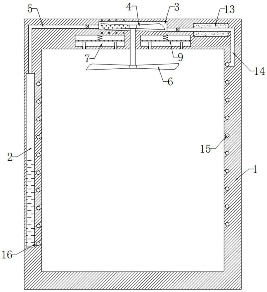
[0032] refer to image 3, different from Embodiment 1, the inner wall of the cabinet body 1 is provided with a spiral chamber 15, the one-way outlet pipe 14 is connected to the upper end of the spiral chamber 15, and the lower end of the spiral chamber 15 is connected to the inner wall of the liquid storage chamber 2 through a connecting pipe 16.

[0033] In this embodiment, the gaseous evaporating liquid flows in the spiral chamber 15 after being cooled and liquefied by the cooling chamber 13, which increases the time for the evaporating liquid to flow in the spiral chamber 15. On the one hand, it can better absorb the heat in the cabinet 1 , to reduce the spread of fire, on the other hand, it can speed up the time for the liquid evaporating liquid to evaporate sharply again, further speed up the operating efficiency of the device, and further speed up the fire extinguishing in the cabinet 1.


PUM


Abstract

The invention discloses a high-temperature self-extinguishing power distribution cabinet. The cabinet comprises a cabinet body, a liquid storage cavity is formed in the side wall of the cabinet body;the liquid storage cavity is filled with evaporation liquid; a circular cavity is formed in the upper end of the cabinet body, a plurality of impellers are rotationally connected to the bottom in thecircular cavity through a rotating shaft, the top in the liquid storage cavity is connected with the inner wall of the circular cavity through a one-way air inlet pipe, a pipe opening of the one-way air inlet pipe is obliquely arranged in the direction of the multiple impellers, and the lower end of the rotating shaft penetrates through the top in the cabinet body and is fixedly connected with multiple fan blades. According to the invention, when a fire occurs in the cabinet body, the impellers rotate when the temperature is high; a spiral coil continuously cuts a magnetic induction line and generates induction current, an electromagnetic plate is magnetized, the electromagnetic plate continuously slides up and down on the inner wall of the material storage cavity, and then a blocking column is driven to continuously slide up and down on the inner wall of a material outlet, so that copper powder is scattered into the cabinet body, the copper powder reacts with oxygen in the cabinet body to generate copper oxide, the concentration of the oxygen in the cabinet body is reduced, and the fire expansion is avoided.

Description

technical field [0001] The invention relates to the technical field of electric equipment, in particular to a high-temperature self-extinguishing type power distribution cabinet. Background technique [0002] The power distribution cabinet is the final equipment of the power distribution system. It is divided into power distribution cabinets and lighting distribution cabinets. There are various electrical components inside the power distribution cabinet to realize the required functions for the power distribution system. [0003] In hot weather, the heat generated by the electronic components in the power distribution cabinet cannot be dissipated in time, which makes it easy to cause fire in the power distribution cabinet, which is easy to cause property loss. In addition, the current power distribution cabinet is designed to prevent The effect of rain and dust prevention makes the heat dissipation holes on the power distribution cabinet smaller, and when a fire occurs in th...

Claims


Application Information

Patent Timeline
Patent Type & Authority Applications(China)
IPC IPC(8): H02B1/56H02B1/28H02B1/30A62C3/16A62C31/00
CPCA62C3/16A62C31/00H02B1/28H02B1/30H02B1/306H02B1/565
Inventor 杨健兵
Owner 圣道天德电气(山东)有限公司
Learn More