Photoelectric system platform with novel plug-in structure

An optoelectronic system and plug-in technology, applied in the field of optoelectronic systems, can solve problems such as failure of key components, performance degradation of optoelectronic equipment, system paralysis, etc., to achieve the effects of improving electromagnetic compatibility, enhancing electrical continuity, reducing noise and power consumption

Pending Publication Date: 2020-10-30
THE 23RD RES INST OF CHINA ELECTRONICS TECH GRP CORP
View PDF0 Cites 0 Cited by
  • Summary
  • Abstract
  • Description
  • Claims
  • Application Information

AI Technical Summary

Problems solved by technology

[0003] One type of equipment uses one chassis. From the perspective of system integration, it is impossible to achieve a high degree of integration of optoelectronic systems. Nowadays, the integration of optoelectronic systems is getting higher and higher. This solution is difficult to be suitable for the integration design of optoelectronic systems with small spaces
[0004] The splicing structure chassis is prone to gaps at the overlapping surfaces, which is prone to electromagnetic leakage, and the electromagnetic shielding effect on internal devices is not good, and cannot meet the complex electromagnetic environment requirements of large integrated optoelectronic systems.
However, many devices in the optoelectronic system are sensitive to electromagnetic interference. The electromagnetic radiation interference or conduction interference of the external environment and the electromagnetic interference between the modules inside the system will lead to the performance degradation of the optoelectronic equipment in the optoelectronic system, and even the failure of some key components. , causing system paralysis
[0005] The photoelectric components in the chassis equipment are generally dissipated by the fan on the back of the chassis, but due to the large internal space of the chassis, the air duct design is difficult to achieve full coverage, resulting in large temperature differences inside the chassis
However, the performance of most of the optical components in the optoelectronic system is greatly affected by the temperature, and the change of temperature will cause the center wavelength shift and the insertion loss of the optical device to increase, etc., which will reduce the optical performance of the system.

Method used


Image

  • Photoelectric system platform with novel plug-in structure
  • Photoelectric system platform with novel plug-in structure
  • Photoelectric system platform with novel plug-in structure

Examples


Embodiment 1

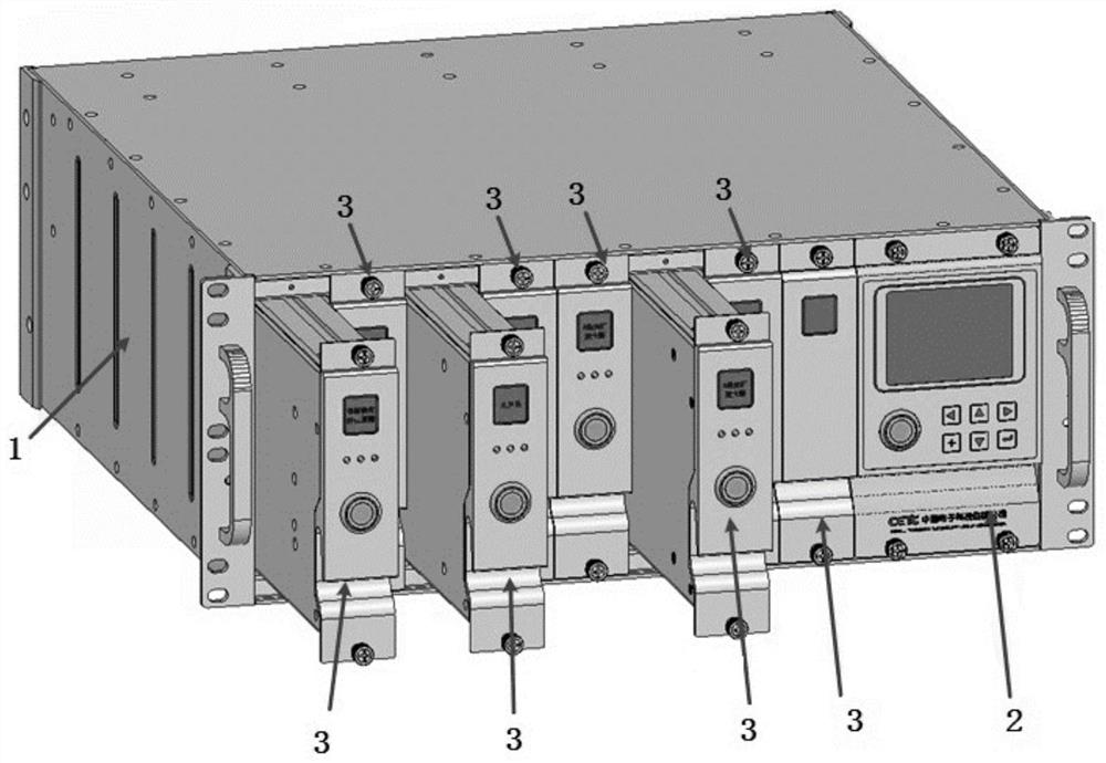
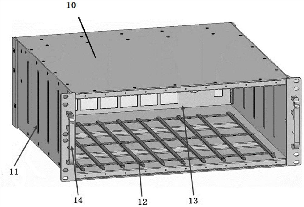
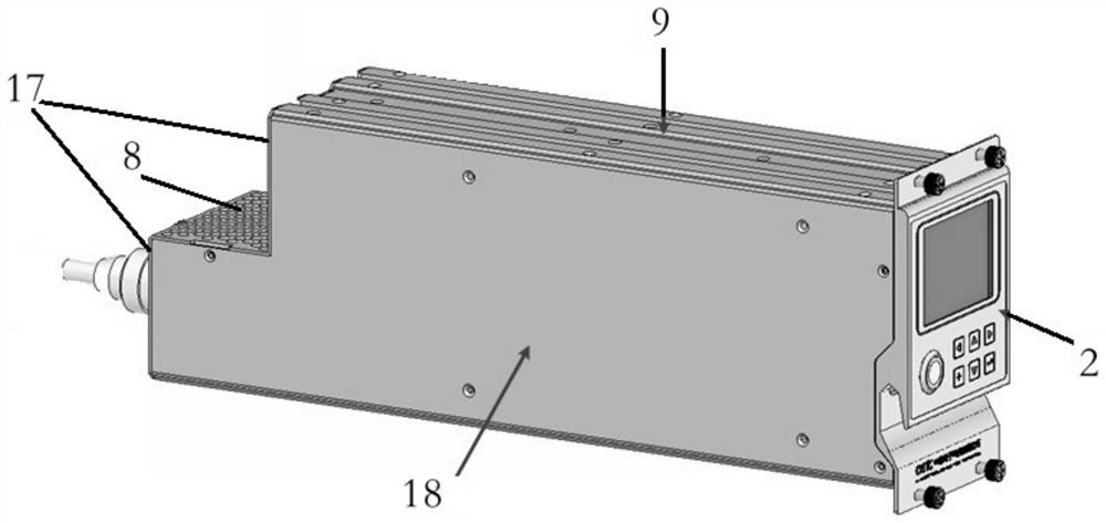
[0040] Subrack 1 in this embodiment adopts a 19-inch 4U chassis, and the front panel of the subrack is as follows: figure 1 The handle shown in the figure is convenient for moving, loading and unloading; the unified back wiring method is adopted to facilitate the unified wiring when installing and using on the rack. The structure of the subrack 1 adopts a modular design, and is composed of a subrack platform 1, a fan module 4, a power supply and control module 2, and 8 general-purpose plug-ins 3 . Among them, the plug-in 3 has a unified structure and interface design, and can be plugged and docked from any slot.

[0041] The plug-in box 1 adopts the "double-layer shielding structure design" in the electromagnetic field shielding structure, and the plug-in structure wrapped by a 2mm thick aluminum alloy forms an "inner shield", and a 4mm thick aluminum alloy metal plate is designed to form a box platform frame. shielding body. The double-layer shielding structure can enhance ...


PUM


Abstract

The invention provides a photoelectric system platform with a novel plug-in structure. The photoelectric system platform is characterized in that the photoelectric system platform comprises a metal plug-in box, wherein a plurality of plug-ins are arranged in the plug-in box in a pluggable installation mode through guide rails, a plurality of plug-ins are of metal box-shaped structures, optical orelectrical interfaces are arranged on backs of the plug-ins, a power supply and control module is installed in one plug-in, optical and electrical component modules are arranged in the other plug-in,and the power supply and control module is used for being connected with external power supply and communication, providing required power supply for the optical and electrical component modules in the other plug-in, establishing communication with the optical and electrical component modules and realizing real-time monitoring, and a fan module is further arranged in the plug-in box and provided with a front air inlet channel and a rear air outlet channel. The photoelectric system platform has advantages of high integration level, strong universality, excellent electromagnetic compatibility, good heat dissipation, capability of achieving heat balance in a short time and smaller internal temperature difference.

Description

technical field [0001] The invention relates to the field of optoelectronic systems, in particular to a novel plug-in structure optoelectronic system platform. Background technique [0002] In general optoelectronic systems, the equipment mostly adopts alloy profile splicing structure chassis, that is, the chassis is composed of left and right side panels, lower bottom plate and front and rear panels, and most of them are one kind of equipment and one chassis. This method is relatively simple to realize, but there are many Defects. [0003] The method of using one chassis for one device cannot achieve a high degree of integration of the optoelectronic system from the perspective of system integration. Nowadays, the integration level of optoelectronic systems is getting higher and higher. [0004] The splicing structure chassis is prone to gaps at the overlapping surfaces, prone to electromagnetic leakage, and has poor electromagnetic shielding effect on internal devices, wh...

Claims


Application Information

Patent Timeline
Patent Type & Authority Applications(China)
IPC IPC(8): H05K7/14H05K9/00H05K7/20
CPCH05K7/1418H05K7/1424H05K7/1435H05K7/1439H05K7/20145H05K7/20172H05K9/0049
Inventor 邢美术林兆培王锐吕方吴凯陈佳林
Owner THE 23RD RES INST OF CHINA ELECTRONICS TECH GRP CORP
Why Eureka
Try Eureka