Vacuum mechanical automatic mixing equipment

A technology of mixing equipment and machinery, applied in mixers, mixer accessories, chemical instruments and methods, etc., can solve the problems of slow discharge, waste, and time-consuming, and achieve the effect of avoiding material residue, avoiding waste, and fast speed.

Inactive Publication Date: 2020-11-03
SOUTHEAST UNIV
View PDF7 Cites 0 Cited by
  • Summary
  • Abstract
  • Description
  • Claims
  • Application Information

AI Technical Summary

Problems solved by technology

[0004] Although the above mixing equipment can realize the mixing of materials in a vacuum state, there are still the following disadvantages in actual use: when the mixing equipment is mixing materials, the materials may accumulate in the tank, which makes the material mixing uneven and cannot be realized. Omni-directional mixing; the material will remain on the inner wall of the tank during mixing, and it cannot be completely removed in the later discharge, which will cause waste; the discharge speed is slow, time-consuming and low-efficiency

Method used


Image

  • Vacuum mechanical automatic mixing equipment
  • Vacuum mechanical automatic mixing equipment
  • Vacuum mechanical automatic mixing equipment

Examples


Embodiment 1

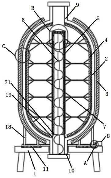
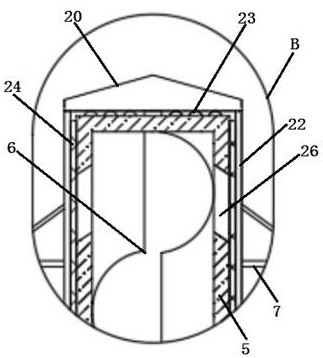
[0021] Embodiment 1: see figure 1 , figure 2 , image 3 , Figure 4 , a vacuum mechanical automation mixing equipment provided by the present invention is now described, which includes a support platform 1 and a tank body 2 provided on the upper end of the support platform 1, and a first magnet is evenly arranged on the outer end wall of the tank body 2. Plate 3, close to the inner end wall of the tank body 2 and evenly provided with a second magnet plate 4, the middle side of the inner end of the tank body 2 is vertically provided with a lifting tube 5 and the lifting tube 5 is provided with a There is a lifter 6, a mixing support rod 7 is provided between the second magnet plate 4 and the material lifting pipe 5, and a driving motor 8 is provided at the upper end of the support table 1.

Embodiment 2

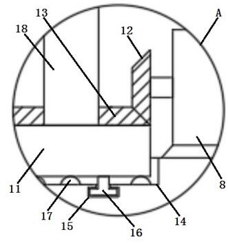
[0022] Example 2: see figure 1 , figure 2 , a kind of vacuum mechanical automatic mixing equipment provided by the present invention is now described, the top of the tank body 2 is equipped with a feeding pipe 9, and the bottom end is equipped with a discharge pipe 10, and the middle part of the upper end of the support table 1 has a circular opening, so The discharge pipe 10 is fixedly installed in the circular opening, the upper end of the support table 1 is provided with an annular seat 11, and the driving motor 8 is arranged on the side of the annular seat 11, and the output shaft of the driving motor 8 corresponds to The position of the ring seat 11 is set, the drive gear 12 is installed outside the output shaft of the drive motor 8, and the ring gear 13 is installed on the outer end wall of the ring seat 11 corresponding to the position of the drive gear 12. The drive gear 12 It is meshed with the ring gear 13 for transmission, and the end of the feed end of the feedin...

Embodiment 3

[0023] Embodiment 3: see figure 1 , figure 2 Now, a vacuum mechanical automation mixing equipment provided by the present invention will be described. The upper end of the support table 1 is provided with an annular rotating groove 14, and the annular seat 11 is movably placed in the rotating groove 14. The rotating groove 14 The inner bottom end is provided with an annular limiting groove 15, and the lower end of the annular seat 11 is evenly provided with a limiting rotating rod 16, and a first The ball 17, the first magnet plate 3 is installed on the upper end of the ring seat 11 through the support column 18.


PUM


Abstract

The invention discloses vacuum mechanical automatic mixing equipment, and relates to the technical field of material mixing; the equipment comprises a support table, and a tank body arranged at the upper end of the support table; wherein first magnet plates are uniformly arranged close to the outer end wall of the tank body in an equal-radian manner, and second magnet plates are uniformly arrangedclose to the inner end wall of the tank body in an equal-radian manner, a material lifting pipe is vertically arranged on the middle side of the inner end of the tank body, a lifter is arranged in the material lifting pipe, a mixing supporting rod is arranged between the second magnet plate and the material lifting pipe, and a driving motor is arranged at the upper end of the supporting table. Bymeans of the mixing equipment, a vacuum mixing environment can be conveniently formed in the tank body, meanwhile, horizontal mixing and vertical material lifting are matched with each other, so thatmaterials can be mixed more uniformly and thoroughly, the operation time is shortened, and the efficiency is improved. In addition, during discharging, materials can be prevented from remaining in the equipment, waste is avoided, and discharging is more thorough.

Description

technical field [0001] The invention relates to the technical field of material mixing, in particular to a vacuum mechanical automatic mixing equipment. Background technique [0002] During material processing, various raw materials need to be mixed and used. The existing mixing methods are generally manual mixing or mixing with a simple mixer. A large number of air bubbles will be generated during the mixing process, which cannot be used directly, and the degree of automation in the operation process is low. , relatively laborious. When stirring substances in existing vacuum tanks, it is also necessary to open the end cover of the tank body, so as to realize the stirring of the substances in the tank, so that outside air can easily enter into it, which will affect the mixing of internal materials. [0003] Existing technology A vacuum mechanical automation mixing equipment (patent number: ZL201920524242.9), including a base plate, a support rod is fixedly installed on the ...

Claims


Application Information

Patent Timeline
IPC IPC(8): B01F13/06B01F13/08B01F15/00
CPCB01F33/70B01F33/453B01F35/121
Inventor 万亚明庄伟超
Owner SOUTHEAST UNIV
Why Eureka
Try Eureka