Hoisting inclined wedge with detachable stop block

A technology of stoppers and wedges, applied in forming tools, manufacturing tools, transportation and packaging, etc., can solve the problems of error accumulation, small mounting surface of the pressing end of the slider, and large height of the driving components, so as to improve the impact resistance Excellent ability, high guiding precision and large sliding area

Pending Publication Date: 2020-11-03
武汉科尔精密科技有限公司
View PDF0 Cites 3 Cited by
  • Summary
  • Abstract
  • Description
  • Claims
  • Application Information

AI Technical Summary

Problems solved by technology

[0004] The above-mentioned structure has the advantages of simple structure, easy processing, and high punching force, but it also has the following disadvantages: 1) Due to the limiting effect of the concave chute, the slider cannot be removed from the rear along the sliding direction, which brings inconvenience to the wedge maintenance. Inconvenient; 2) The slide block is only equipped with a sliding surface on the bottom surface, which cannot bear the lateral force; 3) The height of the driving component is too high, the manipulator cannot pass through, or needs to go around; 4) The installation surface of the pressing end of the slide block is small, It cannot meet the requirements of the mold for installing more tools on the wedge; 5) The stroke of the slider is designed according to ST (the sliding distance of the slider along the sliding surface of the base) as an integer, resulting in the working stroke of the slider WT (sliding distance) calculated based on the triangular relationship The sliding distance of the block along the drive block) is a decimal, which is inconvenient for customers to use, and it is easy to accumulate errors due to decimal rounding

Method used


Image

  • Hoisting inclined wedge with detachable stop block
  • Hoisting inclined wedge with detachable stop block
  • Hoisting inclined wedge with detachable stop block

Examples


Embodiment 1

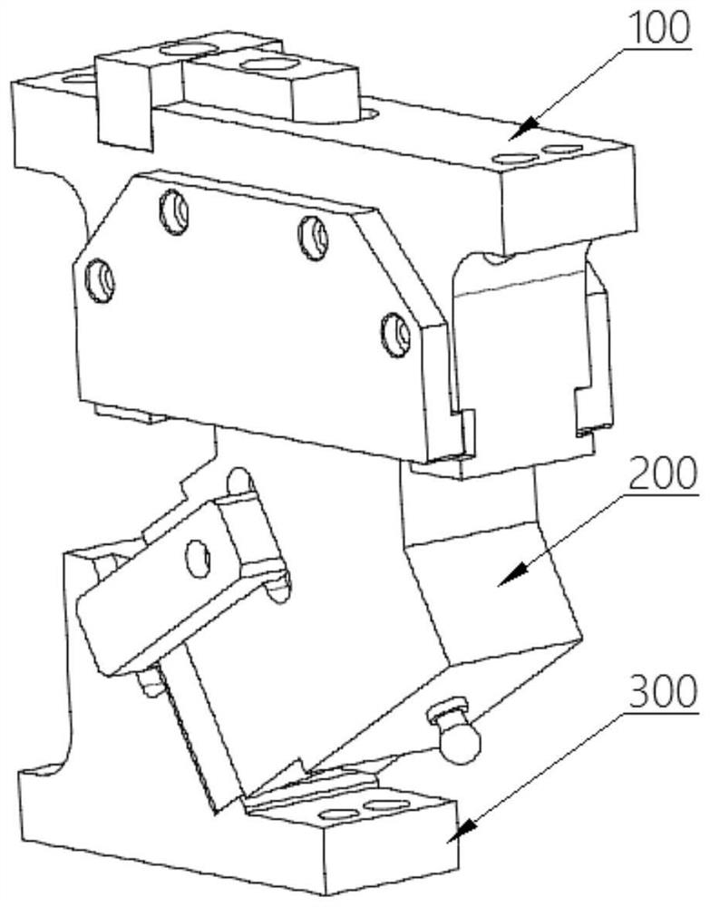
[0038] Such as Figure 2-6 As shown, this embodiment discloses a lifting wedge with a working face width of 100 mm and a hanging platform stop block. The lifting wedge includes a base assembly 100 , a slider assembly 200 and a drive assembly 300 . in:

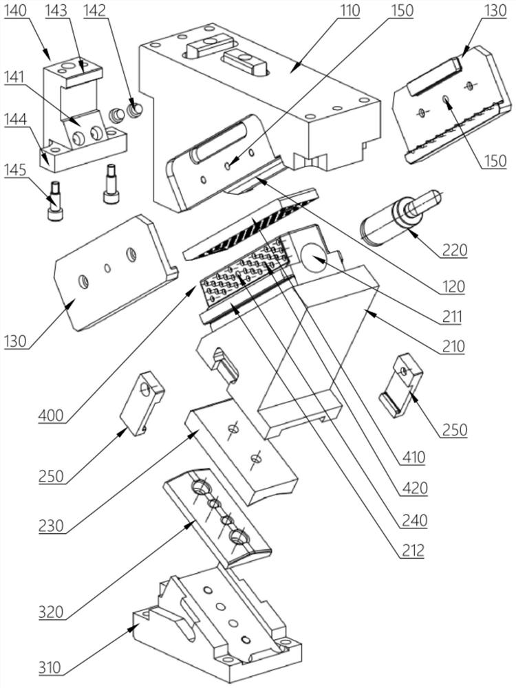
[0039] The base assembly 100 includes a base 110 and a limiting side plate 130. The base 110 is provided with a chute 120, one end of the chute 120 is closed, the other end is set to be open, and a stop block 140 is detachably provided at the open end. . A rubber buffer 142 is provided on the side of the stop block 140 facing the sliding groove 120 for buffering the retracted slider 210 .

[0040]The slider assembly 200 includes a slider 210 , a spring 220 (using a nitrogen gas spring), a first V-shaped guide plate 230 and a forced returner 250 . The top of slide block 210 is installed in the chute 120 of base 110 , and one end of spring 220 is fixed in the slide block hole 211 of slide block 210 upper end with screw, and t...

Embodiment 2

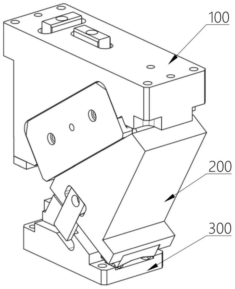
[0050] Such as Figure 7-9 As shown, this embodiment discloses a lifting wedge with a working face width of 100 mm and a boss-type stop block.

[0051] The angle between the bottom surface of the wedge chute and the horizontal direction is less than 45 degrees, so the boss type stop block is adopted, and the protruding direction of the stop boss 143 is vertically upward. Meanwhile, the upper ends of both sides of the nut seat 144 are also provided with The vertically upward bosses and the upper and lower bosses are respectively connected with the vertically downward opening grooves on the base 110 to form a horizontal limit, which greatly improves the bearing strength in the horizontal direction.

[0052] All the other are identical with embodiment 1.

Embodiment 3

[0054] Such as Figure 10-12 As shown, this embodiment discloses a lifting wedge with a working surface width of 350 mm and a hanging platform stop block.

[0055] Due to the large width of the working face, in order to ensure the stability of lateral guide sliding, this embodiment has made the following improvements on the basis of embodiment 1:

[0056] 1) The guide-sliding structure 400 includes four guide plates 410 and a guide key 430. Two parallel guide plates 410 are used between the top of the slider 210 and the bottom surface of the chute 120 to guide the slide. Guide key 430 to improve guide accuracy. The guide key 430 is installed on the keyway at the bottom of the chute 120 with screws, and is matched with the keyway at the top of the slider 210. The guide key has not only increased the guiding accuracy, but also increased the ability of the wedge to bear lateral force; at the same time, the slide Both sides of the block are also provided with guide plates 410, a...


PUM


Abstract

The invention discloses a hoisting inclined wedge with a detachable stop block. The hoisting inclined wedge comprises a base assembly, a sliding block assembly and a driving assembly; the base assembly comprises a base and a limiting side plate, a sliding groove is formed in the base, the stop block is detachably arranged at the open end of the sliding groove, and a buffer is arranged on the stopblock; the sliding block assembly comprises a sliding block and a spring; sliding guide structures are arranged between the top face of the sliding block and the bottom face of the sliding groove andbetween the two side faces and the two side faces of the sliding groove; the stop block is provided with a stop boss and a nut seat, and the nut seat is fixed on the base through a screw; the stop boss is arranged at the upper part of the stop block, is mounted in a groove in the base in a matched manner, and can bear component force in the horizontal or vertical direction; and the driving assembly comprises a driving block, and the sliding block and the driving block are guided through a first V-shaped guide plate and a second V-shaped guide plate. The hoisting inclined wedge has the advantages of being convenient to disassemble and assemble, capable of bearing large impact force and lateral force and the like.

Description

technical field [0001] The invention relates to a wedge, in particular to a lifting wedge with a detachable stop block. Background technique [0002] The wedge mechanism is a mechanical mechanism that changes vertical motion into horizontal motion or inclined motion, and is widely used in the mold industry. As molds become more and more mature in the automobile manufacturing industry, the mold cost and quality control requirements are also getting higher and higher, and then the space occupation of the wedge, the carrying capacity (including punching force, lateral force, stamping speed and wedge material) , strength, etc.), the size of the working face, the size of the return force, and the convenience of wedge maintenance, etc., put forward higher requirements. [0003] Such as figure 1 As shown, the existing cam mechanism currently on the market is generally composed of three parts: a base assembly 100 , a slider assembly 200 and a drive assembly 300 . Wherein, the upp...

Claims


Application Information

Patent Timeline
Patent Type & Authority Applications(China)
IPC IPC(8): B21D37/12B21D53/88F16F15/08
CPCB21D37/12B21D53/88F16F15/08
Inventor 刘电飞张丽杨光明朱然涛张忠武张彩霞李道秀马东阳
Owner 武汉科尔精密科技有限公司
Why Eureka
Try Eureka