Water source heat pump sludge drying device

A technology of sludge drying and water source heat pump, which is applied in dehydration/drying/concentration sludge treatment, chemical instruments and methods, and the use of liquid separation agents, etc., and can solve problems such as large volume, inoperability, and environmental impact

Pending Publication Date: 2020-11-03
绵阳吉华环境工程技术有限公司
View PDF0 Cites 2 Cited by
  • Summary
  • Abstract
  • Description
  • Claims
  • Application Information

AI Technical Summary

Problems solved by technology

[0003] 1) Due to the large volume of the air source heat pump evaporator, it has a great impact on the layout of the heat pump, and the maintenance space is extremely tight
[0004] 2) Since the air source heat pump drying device is composed of multiple heat pump air source units, it is difficult for the hot air from the evaporators of each heat pump unit to be evenly distributed among the evaporators of each unit, which may easily cause the temperature and pressure of some units to exceed the limit alarm shutdown
[0005] 3) Since the air source heat pump evaporator cools and dehumidifies the circulating air passing through the dryer, the dust carried in the cooling saturated circulating

Method used


Image

  • Water source heat pump sludge drying device
  • Water source heat pump sludge drying device

Examples


Embodiment Construction

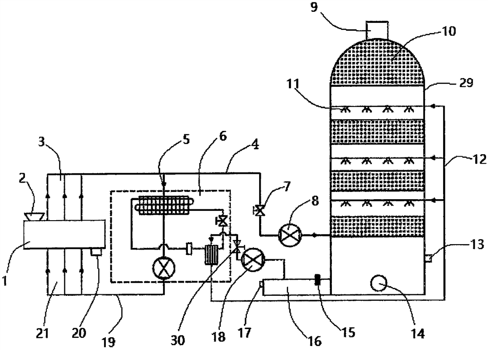
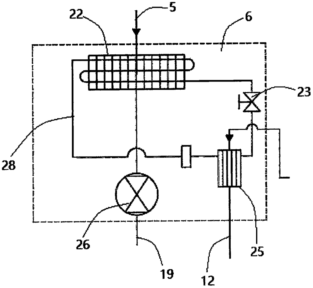
[0021] Embodiments of the present invention are described in detail below, examples of which are shown in the drawings, wherein the same or similar reference numerals designate the same or similar elements or elements having the same or similar functions throughout. The embodiments described below by referring to the figures are exemplary and are intended to explain the present invention and should not be construed as limiting the present invention. In the description of the present invention, it should be understood that the orientation or positional relationship indicated by the terms "upper", "lower", "front", "upper surface" etc. is based on the orientation or positional relationship shown in the drawings, and is only In order to facilitate the description of the present invention and simplify the description, it does not indicate or imply that the device or element referred to must have a specific orientation, be constructed and operated in a specific orientation, and thus...


PUM


Abstract

The invention discloses a water source heat pump sludge drying device which comprises a drying machine, and an air outlet and an air inlet are formed in the drying machine; the air outlet is connectedand communicated with an arranged spray tower through an arranged moisture removal air pipeline; a water source heat pump unit is arranged between the drying machine and the spray tower; wherein thewater source heat pump unit is connected and communicated with the air outlet through an arranged circulating air pipe; meanwhile, a spray head is arranged in the spray tower, spray water is sprayed to humid air sent by the moisture removal air pipeline through the spray head and exchanges heat with a heat source in the humid air, and then the exchanged heat source is sent to the interior of the water source heat pump unit, and the other end of the water source heat pump unit supplies circulating air for supplementing and heating a heat source in the water source heat pump unit again into thedrying machine through an arranged circulating fan, so that sludge in the drying machine is dried; after being deodorized, dedusted and demisted by the interlayer functional filler in the tower, the moisture removal air cooled by contact heat exchange of spray water is discharged according to the national emission standard.

Description

technical field [0001] The invention relates to the technical field of sludge treatment, in particular to a water source heat pump sludge drying device. Background technique [0002] The existing air source heat pump sludge drying technology mainly consists of a sludge dryer and an air source heat pump; The circulating air is cooled and dehumidified, and the heat energy is recovered), and the cooled circulating air is reheated (through the heat pump condenser) and enters the closed circulation air drying mode of the dryer to dry materials. The disadvantages of the prior art are: [0003] 1) Due to the large volume of the air source heat pump evaporator, it has a great impact on the layout of the heat pump, and the maintenance space is extremely tight. [0004] 2) Since the air source heat pump drying device is composed of multiple heat pump air source units, it is difficult to evenly distribute the hot air from the evaporators of each heat pump unit to the evaporator of ea...

Claims


Application Information

Patent Timeline
IPC IPC(8): C02F11/13B01D47/06B01D53/18
CPCB01D47/06B01D53/18B01D2252/103B01D2257/90C02F11/13
Inventor 李化成
Owner 绵阳吉华环境工程技术有限公司
Why Eureka
Try Eureka