Flexible glass cutting device

A cutting device and glass technology, which is applied in glass cutting devices, glass manufacturing equipment, manufacturing tools, etc., can solve the problems of inability to adjust the size and thickness of glass, so as to avoid hand scratches, reduce work intensity, and facilitate placement Effect

Inactive Publication Date: 2020-11-03
哈尔滨市阿城区胜达建筑材料厂
View PDF1 Cites 2 Cited by
  • Summary
  • Abstract
  • Description
  • Claims
  • Application Information

AI Technical Summary

Problems solved by technology

[0005] 3. The invention can only cut glass in a straight line
[0006] 4. The invention cannot be adjusted for the size and thickness of the glass

Method used


Image

  • Flexible glass cutting device
  • Flexible glass cutting device
  • Flexible glass cutting device

Examples


specific Embodiment approach 1

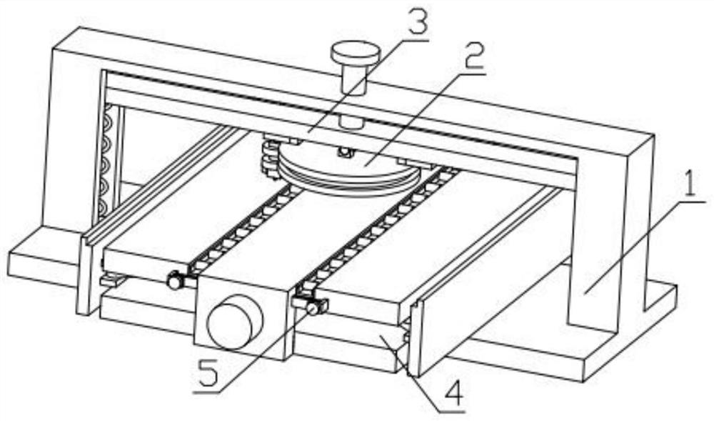
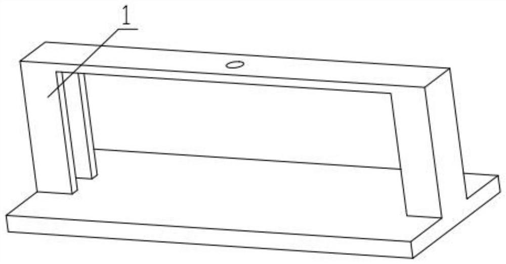
[0039] Combine below Figure 1-15Describe this embodiment, a flexible glass cutting device, including an installation frame 1, a cutting mechanism 2, an extruding mechanism 3, a glass fixing mechanism 4 and a convenient pushing mechanism 5, and the cutting mechanism 2 is slidably installed on the extruding mechanism 3 , the extrusion mechanism 3 is fixedly installed on the installation frame 1, the glass fixing mechanism 4 is fixedly installed on the installation frame 1, and the convenient pushing mechanism 5 is fixedly installed on the glass fixing mechanism 4.

specific Embodiment approach 2

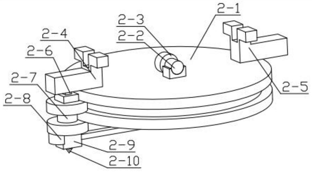
[0041] Combine below Figure 1-15 Describe this embodiment, this embodiment will further explain Embodiment 1, the described cutting mechanism 2 includes a grooved disc 2-1, a moving motor 2-2, a motor gear 2-3, a sliding foot 2-4, a sliding Foot two 2-5, triangular plug-in 2-6, limit piece 2-7, track rod 2-8, ring slide 2-9, diamond 2-10, set screw 2-11, support spring 2-12, belt The two ends of the grooved disc 2-1 are respectively fixedly equipped with a sliding foot one 2-4 and a sliding foot two 2-5, the mobile motor 2-2 is fixedly installed on the grooved disc 2-1, and the motor gear 2-3 is fixed Installed on the output end of the mobile motor 2-2, the limiter 2-7 is slidably installed in the groove provided on the grooved disc 2-1, and the limiter 2-7 is fixedly installed on one end of the track rod 2-8 , the other end of the track bar 2-8 is rotatably installed in the groove provided on the grooved disc 2-1, the ring slider 2-9 is slidably installed on the track bar 2...

specific Embodiment approach 3

[0043] Combine below Figure 1-15 This embodiment will be described. This embodiment will further describe the second embodiment. The extrusion mechanism 3 includes an extrusion screw 3-1, a beam 3-2, a tooth strip 3-3, a side spring 3-4, and a tooth Stripes 3-3 are fixedly installed on the crossbeam 3-2, and the crossbeam 3-2 is respectively slidably installed with sliding foot 1 2-4 and sliding foot 2 2-5, and the two ends of the crossbeam 3-2 are respectively fixedly installed with side springs 3-4, the other end of the side spring 3-4 is fixedly installed on the installation frame 1, the beam 3-2 is slidably installed in the groove provided on the installation frame 1, and the extrusion screw 3-1 is threadedly connected with the installation frame 1, The extruding screw 3-1 passes through the mounting frame 1 and is in contact with the beam 3-2, and the motor gear 2-3 is meshed with the toothed strip 3-3.


PUM


Abstract

The invention relates to the related field of glass processing, in particular to a flexible glass cutting device which comprises an installation frame, a cutting mechanism, an extrusion mechanism, a glass fixing mechanism and a convenient pushing mechanism. The cutting mechanism is installed on the extrusion mechanism in a sliding mode, and the extrusion mechanism is fixedly installed on the installation frame. The glass fixing mechanism is fixedly mounted on the installation frame, and the convenient pushing mechanism is fixedly mounted on the glass fixing mechanism. The device has the function of cutting glass with different sizes and thicknesses, has the function of cutting circles with different diameters, has the function of correcting and fixing the position of the glass, and has thefunction of conveniently pushing the glass on an operation table.

Description

technical field [0001] The invention relates to the field of glass processing, in particular to a flexible glass cutting device. Background technique [0002] Glass is an amorphous inorganic non-metallic material, generally made of various inorganic minerals (such as quartz sand, borax, boric acid, barite, barium carbonate, limestone, feldspar, soda ash, etc.) Yes, the glass needs to be cut before it is put into use. The inventors found that in the prior art, the pending patent No. is CN202010619851. There are the following disadvantages. [0003] 1. This invention cannot provide help for the placement of the glass, and can only rely on manual force to perform the straightening operation of the glass. [0004] 2. The position of the glass is adsorbed and fixed by the pneumatic adsorption component, but it does not have the function of correcting the glass. It is still necessary to manually correct the position of the glass to avoid glass deviation. [0005] 3. This invent...

Claims


Application Information

Patent Timeline
Patent Type & Authority Applications(China)
IPC IPC(8): C03B33/04
CPCC03B33/04
Inventor 高会明
Owner 哈尔滨市阿城区胜达建筑材料厂
Why Eureka
Try Eureka