Grid type box soft steel damper applied to bridges and structural engineering

A mild steel damper and structural engineering technology, applied in bridges, bridge parts, bridge construction, etc., can solve problems such as limited seismic capacity of bridges, damage of bridge support columns, and impact on safe use of bridges, so as to avoid damage and ensure stability Effect

Active Publication Date: 2020-11-03
中建协和建设有限公司
View PDF6 Cites 1 Cited by
  • Summary
  • Abstract
  • Description
  • Claims
  • Application Information

AI Technical Summary

Problems solved by technology

[0003] When the current bridges are built in different geological regions, unexpected earthquakes will occur in some areas due to different geographical locations. If the impact force of the earthquake on the bridge cannot be buffered in time, it is easy to cause the supporting columns of the bridge to be damaged. The bottom of the bridge surface is broken or shifted, causing the main body of the bridge support column to be damaged, which affects the safe use of the entire bridge. The force at the connection between the columns is constantly changing. If the seismic buffering capacity of the bridge damper cannot be further improved, the seismic capacity of the entire bridge will be very limited.

Method used


Image

  • Grid type box soft steel damper applied to bridges and structural engineering
  • Grid type box soft steel damper applied to bridges and structural engineering
  • Grid type box soft steel damper applied to bridges and structural engineering

Examples


Embodiment 1

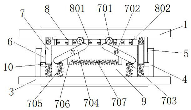
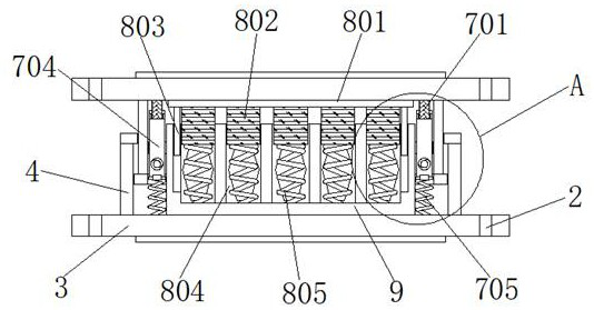
[0030] Example 1, such as figure 1 , 3 , 4, 5 and 7, when the top of the upper connecting plate 1 is subjected to a larger force, the upper connecting plate 1 drops a little distance, the slider 803 slides downward inside the chute 806, and the movable rod 802 moves in the square The inside of the groove 804 slides down a little. At this time, the shock absorbing spring 805 is shortened by force and stores a certain amount of elastic potential energy to buffer the force on the upper connecting plate 1. If the force on the upper connecting plate 1 is relatively large, the upper connecting plate 1 When the bottom of the plate 1 is in contact with the top of the outer limit ring 5, a part of the force received by the upper connecting plate 1 will be transmitted to the body of the installation warehouse 9. Since the inside of the square groove 804 is uniformly provided with a plurality of groups of through holes 808, and through A "Z" shaped ductile steel rod 807 is arranged insi...

Embodiment 2

[0031] Example 2, such as Figure 1-3 As shown, when the force on the upper connecting plate 1 is constantly changing, the distance between the upper connecting plate 1 and the lower connecting plate 3 is continuously shortened or elongated slightly, so that the roller 701 is constantly rolling back and forth on the bottom of the upper connecting plate 1 , the connecting rod 704 is forced to continuously rotate forward and backward at a certain angle with the rotating shaft 702 as the axis, and when the two sets of rollers 701 roll close to each other, the buffer spring A 705 is stretched to store elastic potential energy, and the buffer spring B 707 is also connected by the two groups The rod 704 is elongated to store elastic potential energy, and when the distance between the upper connecting plate 1 and the lower connecting plate 3 increases slightly, the two sets of rollers 701 roll away from each other, and at this time, the buffer spring A 705 and the buffer spring B 707 ...


PUM


Abstract

The invention discloses a grid type box soft steel damper applied to bridges and structural engineering. The grid type box soft steel damper comprises a lower connecting plate, a mounting bin is arranged in the middle of the top of the lower connecting plate, an outer sleeve bin is arranged at the edge of the top of the lower connecting plate, and an outer limiting ring is arranged at the top of the outer sleeve bin; and an inner sleeve bin is arranged on the inner side of the outer sleeve bin, and an upper connecting plate is arranged at the top of the inner sleeve bin. According to the gridtype box soft steel damper, through cooperative use of the upper connecting plate, fixing holes, the lower connecting plate, an energy absorption and shock absorption assembly and the mounting bin, when the distance between the upper connecting plate and the lower connecting plate is slightly changed, force borne by the bridges is transmitted to shock absorption springs through movable rods, and the force borne by the damper is buffered through the shock absorption springs, so that the stability of connection between bridge supporting columns and the bottom of a bridge deck is greatly guaranteed, the bridges are prevented from being damaged due to excessive stress, and the safe use of the whole bridges is guaranteed.

Description

technical field [0001] The invention relates to the technical field of mild steel dampers, in particular to a palace-style box-type mild steel damper applied to bridges and structural engineering. Background technique [0002] my country is located at the junction of the circum-Pacific seismic belt and the Eurasian seismic belt, and is an earthquake-prone country. In order to minimize the losses caused by earthquake disasters, it is necessary to carry out seismic design and reinforcement of engineering structures such as buildings and bridges. The traditional seismic design is to use the deformation of the structure itself to resist and consume earthquake energy to meet the seismic requirements of the structure. The control technology is to add a specific energy-dissipating element to the structure. Under the action of an earthquake, the structure mainly relies on the specific energy-dissipating element to absorb and dissipate the seismic energy introduced into the structure...

Claims


Application Information

Patent Timeline
Patent Type & Authority Applications(China)
IPC IPC(8): F16F15/06F16F15/02F16N21/06F16N37/00E01D19/00E04B1/98E04H9/02
CPCF16F15/063F16F15/022F16N21/06F16N37/00E01D19/00E04B1/98E04H9/02F16N2037/006
Inventor 李石凤
Owner 中建协和建设有限公司
Why Eureka
Try Eureka