Battery structure and battery module

A battery and cell technology, applied in the field of battery structures and battery modules, can solve problems such as the decomposition of battery electrolyte, and achieve the effects of improved sealing, high mechanical strength, and good stability

Pending Publication Date: 2020-11-03
JIANGSU ZENIO NEW ENERGY BATTERY TECH CO LTD
View PDF0 Cites 8 Cited by
  • Summary
  • Abstract
  • Description
  • Claims
  • Application Information

AI Technical Summary

Problems solved by technology

[0005] One of the purposes of the present invention is to provide a battery structure that can avoid the circulation of electrolyte between the battery packs and solve the problem of decomposition of the electrolyte inside the battery due to the high voltage at both ends of the battery. Helps improve battery performance

Method used


Image

  • Battery structure and battery module
  • Battery structure and battery module
  • Battery structure and battery module

Examples


Embodiment approach 1

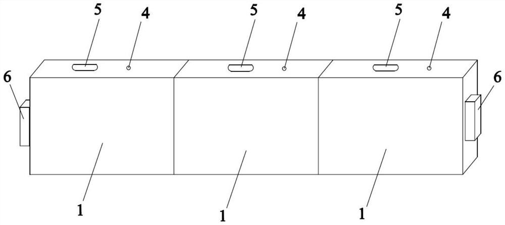
[0029] A battery structure, including several shells 1 with two ends connected, and conductive connectors 2 are fixed between adjacent shells 1, and the shells 1 and the connectors 2 are surrounded by several shells for accommodating batteries. 3, the adjacent cells 3 are electrically connected through the connector 2. Since the battery pack is connected in series, the voltage of the battery will increase with the number of cells inside the battery, resulting in a higher voltage at both ends of the battery. There is a risk of decomposition of the electrolyte inside the battery, which will affect the performance of the cells and even lead to battery safety. questions such as Figure 1~2As shown, therefore, a conductive connecting piece 2 is fixed between adjacent shells 1, and the connecting piece 2 adopts a metal plate structure, which is fixed on both ends of the shell 1 by welding, compared with insulating plates fixed on adjacent Between the shells 1, the shell 1 and the c...

Embodiment approach 2

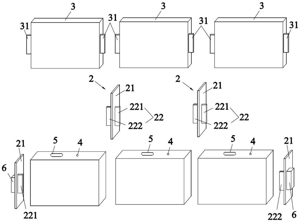
[0038] Such as Figure 3-5 As shown, the difference from the first embodiment is that the first connection part 221 and the second connection part 222 of this embodiment are arranged on both sides of the body 21 in a staggered manner, and correspondingly, the tabs 31 on both sides of the battery cell 3 are arranged in a staggered manner. At least one of a pole 6 , a liquid injection hole 4 and an explosion-proof valve 5 is provided outside the connectors 2 at both ends of the battery structure. The first connecting part 221 and the second connecting part 222 are staggered and placed on both sides of the body 21, which can avoid excessive stress concentration of the first connecting part 221 and the second connecting part 222 at the same position, and contribute to the service life of the connecting part 22. Correspondingly, in order to cooperate with the staggered structure of the first connecting part 221 and the second connecting part 222, the tabs 31 on both sides of the ba...

Embodiment approach 3

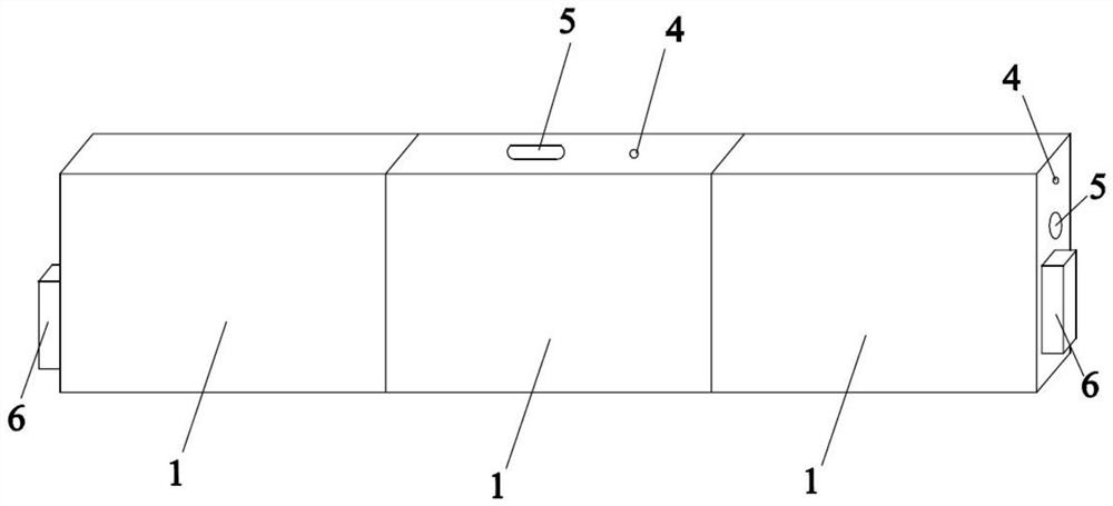
[0041] The difference from Embodiment 1 is that the material of the connecting portion 22 in this embodiment is the same as the current collector material of the pole piece of the electric core 3 to which it is electrically connected, openings are provided at both ends of the housing 1, and the adjacent housing 1 The openings are arranged correspondingly in sequence, the connecting piece 2 is arranged between the two openings, an insulating sheet is arranged under the liquid injection hole 4 and the explosion-proof valve 5, and the insulating sheet is provided with a hollow structure. In this embodiment, the connection part 22 connected to the negative electrode tab 31 is made of copper, and the connection part 22 connected to the positive electrode tab 31 is made of aluminum, so as to ensure that there is no pressure drop caused by material differences and reduce the pressure of the connection part. The production cost of 22; the openings of adjacent shells 1 correspond one by...


PUM


Abstract

The invention belongs to the technical field of battery production and manufacturing, and particularly relates to a battery structure, and the structure comprises a plurality of shells (1) with two communicated ends, wherein conductive connecting pieces (2) are fixed between the adjacent shells (1), and the shells (1) and the connecting pieces (2) enclose a plurality of sealing cavities for accommodating battery cells (3). And the adjacent battery cells (3) are electrically connected through the connecting pieces (2). Electrolyte circulation between the battery packs can be avoided, the problem that electrolyte in the battery is decomposed due to the fact that the voltage at the two ends of the battery is high is solved, and the performance of the battery can be improved. In addition, theinvention also discloses a battery module.

Description

technical field [0001] The invention belongs to the technical field of battery production and manufacturing, and in particular relates to a battery structure and a battery module. Background technique [0002] Today, lithium-ion batteries are characterized by high energy density, long cycle life, low self-discharge, and environmental friendliness. As the country vigorously promotes pure electric vehicles, the application of lithium-ion batteries in pure electric vehicles has also shown explosive growth. In order to promote the rapid development of power battery-related industries and achieve overtaking in the automotive industry, the state has introduced relevant subsidy policies for the new energy industry. The important goal of the subsidy policy is to continuously guide and improve the energy density of the battery system. At present, the improvement of the energy density of the power battery system mainly depends on the improvement of the energy density of the power cel...

Claims


Application Information

Patent Timeline
Patent Type & Authority Applications(China)
IPC IPC(8): H01M2/22H01M2/02H01M2/08H01M50/528
CPCH01M2220/20Y02E60/10
Inventor 袁威姜斌吴志康
Owner JIANGSU ZENIO NEW ENERGY BATTERY TECH CO LTD
Why Eureka
Try Eureka