Portable solar emergency energy storage device

An energy storage device and solar energy technology, applied in the field of solar energy storage, can solve the problems of affecting the illumination effect of solar panels, unfavorable use, unfavorable energy storage, etc., to avoid separation and breakage, ensure normal heat absorption, and ensure stability Effect

Active Publication Date: 2020-11-03
山东鑫泰莱光电有限公司
View PDF9 Cites 0 Cited by
  • Summary
  • Abstract
  • Description
  • Claims
  • Application Information

AI Technical Summary

Problems solved by technology

[0003] At present, when the solar emergency energy storage device is in use, the solar panel is directly placed on the side of the device, and the surface of the device is not equipped with a mechanism for fixing the solar panel. When the battery is charged in a windy weather, the solar panel is easy to blow down. It affects the lighting effect of the solar panel, which is not conducive to energy storage; and the energy storage device is connected by screws. When the battery fixed inside the shell needs to be replaced, the screws of the shell need to be disassembled, which is not conducive to the quick disassembly and replacement of the battery; After the lighting bulb of the emergency device, the bulb and the emergency device need to be placed separately, and the bulb cannot be stored, and the separate placement is not conducive to the next use

Method used


Image

  • Portable solar emergency energy storage device
  • Portable solar emergency energy storage device
  • Portable solar emergency energy storage device

Examples


Embodiment Construction

[0022] In order to make the technical means, creative features, goals and effects achieved by the present invention easy to understand, the present invention will be further described below in conjunction with specific embodiments.

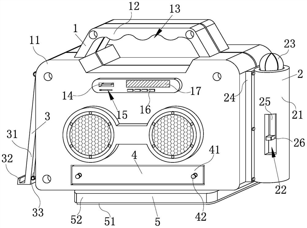
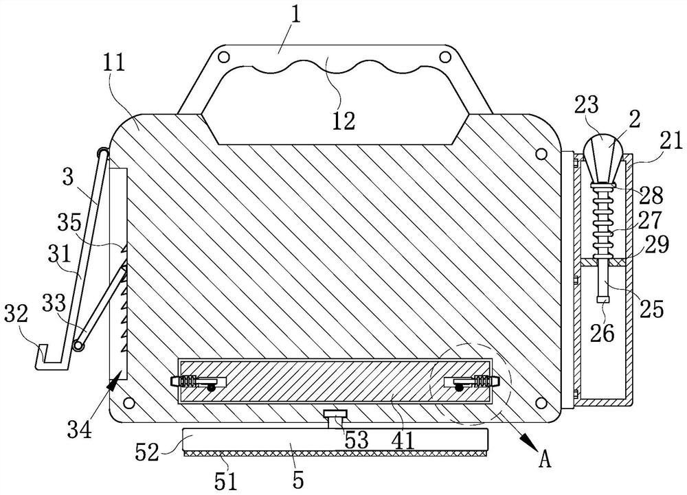
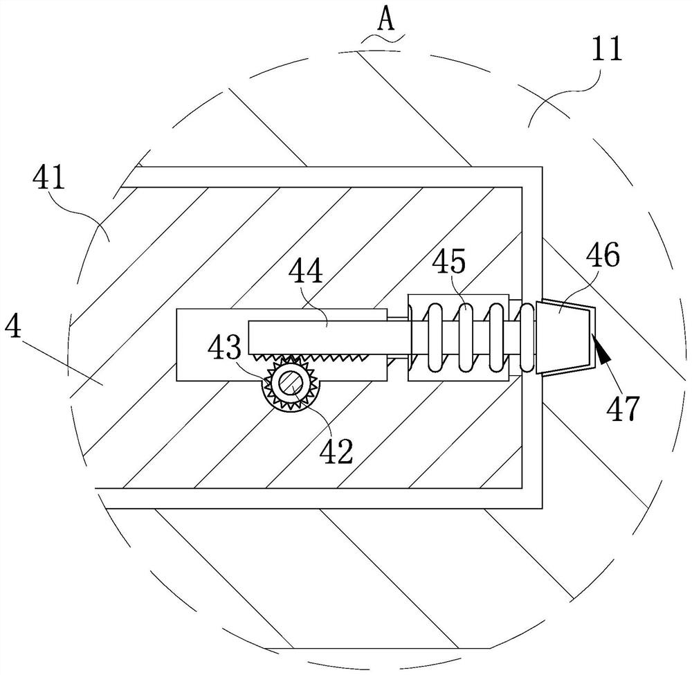
[0023] Such as Figure 1-Figure 5 As shown, a portable solar emergency energy storage device according to the present invention includes an energy storage mechanism 1, a protection mechanism 2, an installation mechanism 3, a battery fixing mechanism 4 and a support mechanism 5, and one side of the energy storage mechanism 1 The wall is rotatably connected with the installation mechanism 3 for fixing the solar panel, and the side wall of the energy storage mechanism 1 away from the installation mechanism 3 is installed with the protection mechanism 2 for storing and protecting the light bulb. The inside of the energy storage mechanism 1 is installed with the battery fixing mechanism 4 for fixing the battery and facilitating battery maintenance. The...


PUM


Abstract

The invention relates to the technical field of solar energy storage, in particular to a portable solar emergency energy storage device which comprises an energy storage mechanism, a protection mechanism, a mounting mechanism, battery fixing mechanisms and a supporting mechanism. During charging, one end of the supporting mechanism is rotationally fixed to the side wall of the energy storage mechanism, a solar cell panel is fixed to the supporting mechanism, the solar cell panel leaning on the side face of the energy storage mechanism is prevented from toppling over in windy days, normal heatabsorption of the solar cell panel is guaranteed, and charging is facilitated; after an illuminating lamp bulb is used, one end of the protection mechanism is pushed to place the lamp bulb into the protection mechanism, so that the lamp bulb is stored, and the lamp bulb is prevented from being separately placed and broken; the battery fixing mechanisms are slidably connected to the side face of the energy storage mechanism, when a battery needs to be replaced and overhauled, the two battery fixing mechanisms are relatively rotated, one ends of the two battery fixing mechanisms are separated from the energy storage mechanism, and disassembly and replacement of the battery are facilitated.

Description

technical field [0001] The invention relates to the technical field of solar energy storage, in particular to a portable solar emergency energy storage device. Background technique [0002] Solar energy is a renewable energy source. Refers to the sun's heat radiation energy, the main performance is often said that the sun's rays. In modern times, it is generally used to generate electricity or provide energy for water heaters. Solar energy is produced by the hydrogen-helium fusion of hydrogen atoms inside the sun and releases huge nuclear energy. Most of the energy needed by humans comes directly or indirectly from the radiant energy from the sun. sun. Plants release oxygen and absorb carbon dioxide through photosynthesis, and convert solar energy into chemical energy and store it in plants. Fossil fuels such as coal, oil, and natural gas are also primary energy sources that evolved from ancient animals and plants buried underground over a long geological period. Solar em...

Claims


Application Information

Patent Timeline
Patent Type & Authority Applications(China)
IPC IPC(8): H02J7/35H02S20/30F21S9/03F21V15/00F21V33/00
CPCH02J7/35H02S20/30F21V33/00F21V15/00F21S9/03Y02E10/50
Inventor 解晓利陈德兰苏明
Owner 山东鑫泰莱光电有限公司
Why Eureka
Try Eureka