
Inspection unmanned aerial vehicle wireless charging system, device and method based on high-voltage line energy taking

A wireless charging and power-taking device technology, applied in circuit devices, charging stations, electric vehicle charging technology, etc., can solve problems such as low system stability, insufficient transmission distance, and insufficient transmission efficiency

Inactive Publication Date: 2020-11-03
JIANGSU FRONTIER ELECTRIC TECH +1
View PDF15 Cites 5 Cited by
  • Summary
  • Abstract
  • Description
  • Claims
  • Application Information

AI Technical Summary

Problems solved by technology

[0007] The invention provides a wireless charging system, device and method for inspection drones based on high-voltage line energy harvesting. The technical problem to be solved is that the existing high-voltage cable charging device and method for inspection drones, the charging platform is not fixed, and the system is stable. Low, unable to resist offset, transmission efficiency is not high enough, transmission distance is not far enough

Method used


Image

  • Inspection unmanned aerial vehicle wireless charging system, device and method based on high-voltage line energy taking
  • Inspection unmanned aerial vehicle wireless charging system, device and method based on high-voltage line energy taking
  • Inspection unmanned aerial vehicle wireless charging system, device and method based on high-voltage line energy taking

Examples


Embodiment 1

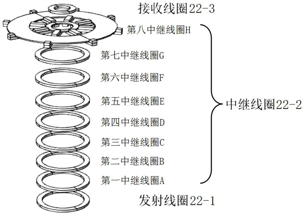
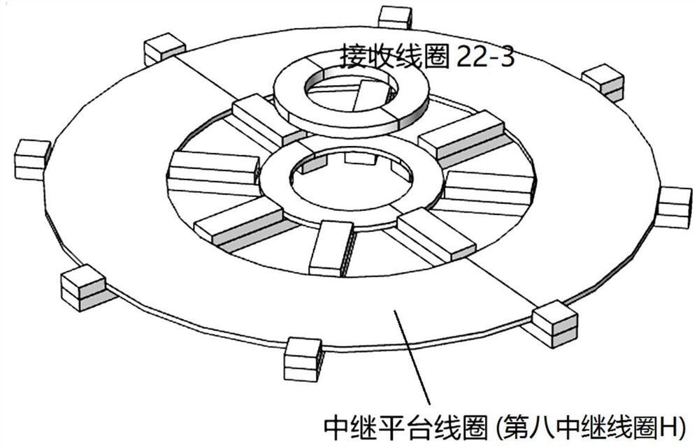
[0052] In order to apply the electromagnetic induction wireless power transmission technology to the wireless charging system for inspection drones based on high-voltage line energy harvesting, this embodiment provides a wireless charging system for inspection drones based on high-voltage line energy harvesting, such as figure 1 As shown in the module structure diagram, it includes a sequentially connected high-voltage power-taking module 1, a wireless power transmission module 2, and a drone charging module 3. The wireless power transmission module 2 includes a sequentially connected primary side voltage adjustment unit 21, a coupling unit 22 and The secondary side voltage adjustment unit 23, the primary side voltage adjustment unit 21 is connected to the high-voltage power-taking module 1, and the secondary side voltage adjustment unit 23 is connected to the UAV charging module 3. Because the high-voltage power-taking module 1 uses an intelligent transformer to get power from...

Embodiment 2

[0080] This embodiment provides a wireless charging device for inspection drones based on high-voltage line energy harvesting, which is used to dock and charge drones, such as Figure 13 As shown, it specifically includes a high-voltage power-taking device 4, a wireless energy transmission device 5, and an induction device 6. The high-voltage power-taking device 4 is installed with a high-voltage power-taking module 1 and a primary side voltage adjustment unit 21 as in the charging system of Embodiment 1; The energy transmission device 5 is equipped with a coupling unit 22, an insulator 24 (the coupling unit 22 is installed in the insulator 24) and a relay charging platform 25 as in the charging system of Embodiment 1; the induction device 6 (corresponding to the load induction unit 12) is fixed in the middle The charging platform 25 is electrically connected to the high-voltage power-taking device 4 .

[0081] Specifically, the relay charging platform 25 is fixed on the utili...

Embodiment 3

[0084] This embodiment provides an inspection UAV based on high-voltage line energy harvesting, such as Figure 15 As shown, it specifically includes the drone body 7, the IC card 8 installed on the upper side of the drone body 7, the coil support 9 installed under the drone body 7, and the receiving coil 22- 3, fixed on the metal shielding layer above the receiving coil 22-3 (installed between the receiving coil 22-3 and the drone body 7, Figure 14 not shown).

[0085] The UAV charging module 3 as described in Embodiment 1 is installed in the UAV body 7, which will not be repeated in this embodiment. The positional relationship of the UAV in this embodiment docked on the wireless charging device described in Embodiment 2 is as follows: Figure 13 As shown, after the induction device 6 recognizes the relevant information on the IC card 8, as described in Embodiment 1, the relevant signal is sent to the primary-side controller 11 through the secondary-side controller 31, so ...


PUM


Abstract

The invention relates to the technical field of wireless charging, and particularly discloses an inspection unmanned aerial vehicle wireless charging system, device and method based on high-voltage line energy taking. The system comprises a high-voltage electricity taking module, a wireless electric energy transmission module and an unmanned aerial vehicle charging module which are connected in sequence. The wireless power transmission module comprises a primary side voltage adjusting unit, a coupling unit and a secondary side voltage adjusting unit which are connected in sequence. The primaryside voltage adjusting unit is connected with the high-voltage electricity taking module, and the secondary side voltage adjusting unit is connected with the unmanned aerial vehicle charging module.The coupling unit comprises a transmitting coil connected with the primary side voltage adjusting unit, a receiving coil connected with the unmanned aerial vehicle charging module, and a multi-stage relay coil arranged between the transmitting coil and the receiving coil. The plurality of relay coils can effectively improve the transmission distance, and in combination with the insulator structure, not only can the requirement for the insulation distance between the high-voltage side and the low-voltage side be ensured, but also the size and the weight of the wireless power transmission moduleare reduced.

Description

technical field [0001] The invention relates to the technical field of wireless charging, in particular to a wireless charging system, device and method for a patrol drone based on high-voltage line energy harvesting. Background technique [0002] In recent years, with the rapid construction of my country's power grid and the rapid development of transmission lines of various voltage levels, in order to ensure the safe operation of the power grid, power inspection is an indispensable task. Compared with the traditional manual inspection, UAV inspection saves a series of high-level complex actions such as manual climbing, and the observation of special phenomena on high-voltage towers and power lines can be done through the PTZ camera on the UAV. Therefore, it has the advantages of safety, high efficiency and precision; secondly, the UAV can fly along the power line at high altitude, and the complex ground environment has no influence on the inspection process of the UAV, whi...

Claims


Application Information

Patent Timeline
Patent Type & Authority Applications(China)
IPC IPC(8): H02J50/12H02J50/50B60L53/12
CPCH02J50/12H02J50/50B60L53/12B60L2200/10Y02T10/70Y02T10/7072Y02T90/14
Inventor 王成亮王智慧徐妍唐春森杨庆胜左志平李小飞贾亚辉
Owner JIANGSU FRONTIER ELECTRIC TECH
Learn More