Wheel pair paint brushing method

A technology for wheel set and painting, applied in the direction of spraying device, etc., can solve problems such as low efficiency, inability to solve, hidden safety hazards, etc., to avoid waste of resources, improve painting efficiency, and improve quality.

Inactive Publication Date: 2020-11-06
HUAINAN MINING IND GRP
View PDF8 Cites 1 Cited by
  • Summary
  • Abstract
  • Description
  • Claims
  • Application Information

AI Technical Summary

Problems solved by technology

[0004] However, the overhaul workshop in the coal mine does not have special equipment for painting the wheelsets. The painting operation is done entirely by manual hand-held cotton cloths and brushes. The wheel sets are painted, which is labor-intensive and takes no less than ten minutes. According to the production schedule of the existing maintenance workshop, at least 20 wheelsets must be painted every day. task, time-consuming and inefficient
[0005] In addition, employees have to wear heavy gas masks and paint for a long time to contact, which will cause great harm to the health of employees. They also need to clean up the paint on the work site at any time.
[0006] The utility model patent with the application number "CN201520802516.8" discloses a steel pipe straightening, derusting and brushing paint purification device, including straightening device 1, upper wheel, lower wheel, control screw, switch, motor, brush cylinder bearing seat, Brush cylinder, wire brush, straightening device 2, paint brushing device, fuel injection nozzle, oil

Method used


Image

  • Wheel pair paint brushing method
  • Wheel pair paint brushing method
  • Wheel pair paint brushing method

Examples


Embodiment 1

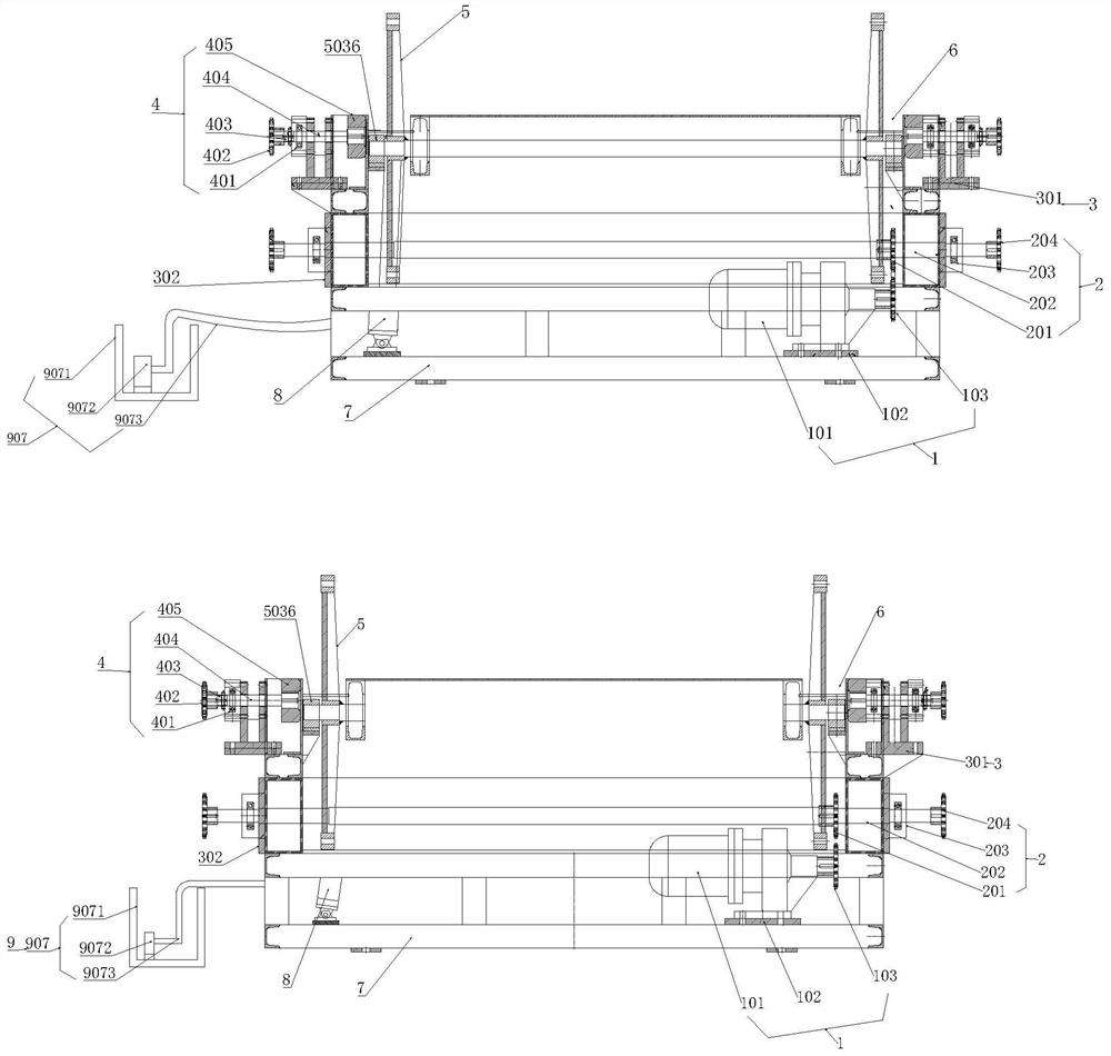
[0073] Such as figure 2 , figure 2 A structural schematic diagram of a wheel set automatic painting device provided in Embodiment 1 of the present invention; a painting method comprising the following steps:

[0074] S1, place the wheelset on the top of the frame structure 7 of the wheelset painting device;

[0075] The wheel set automatic painting device also includes a first driving mechanism 1, a rotating mechanism 2, a fixed assembly 3, a wheel set rolling mechanism 4; a rocker arm assembly 5, a chute 6, a second driving mechanism 8 and a painting device 9 ;in:

[0076]Both sides of the top of the frame structure 7 are symmetrically provided with chute 6 for accommodating wheelsets; the bottom bolt of the frame structure 7 is fixedly provided with a first drive mechanism 1, and the first drive mechanism 1 and the The rotating mechanism 2 on the frame structure 7 is connected and drives the rotating mechanism 2 to rotate; the fixed assembly 3 is fixed on the side of th...

Embodiment 2

[0117] refer to Figure 13 , Figure 13 A schematic circuit diagram of a wheel set automatic painting device provided in an embodiment of the present invention; the present invention also includes a painting control circuit, the painting control circuit includes a chip control module and a motor control module, and the chip control module and Electrical connection of the motor control module;

[0118] The model of the chip control module is CP1E-E40SDR-A; the L1 pin of the chip control module is connected to the neutral line N;

[0119] Wherein, the motor control module includes a button switch S0, a fuse FU1, a fuse FU2, a fuse FU3, an AC contactor KM0, an AC contactor KM1, an AC contactor KM2, a motor M1, and a motor M2. KM0 includes a coil KM01 and a normally open contact KM02; the AC contactor KM1 includes a coil KM11 and a normally open contact KM12; the AC contactor KM2 includes a coil KM21 and a normally open contact KM22; wherein the live line L3 and One end of the fu...

Embodiment 3

[0127] refer to Figure 12 , Figure 12 The pneumatic principle diagram of a wheel set automatic painting device provided by the embodiment of the present invention; also includes a pneumatic system, the pneumatic system includes a pneumatic triple piece, an electromagnetic reversing valve Y1, an electromagnetic reversing valve Y2, an electromagnetic reversing valve Y3; wherein, the pneumatic triple piece is respectively connected with the air inlet P1 of the electromagnetic reversing valve Y1, the air inlet P2 of the electromagnetic reversing valve Y2, and the air inlet P3 of the electromagnetic reversing valve Y3;

[0128] The air outlet A1 of the electromagnetic reversing valve Y1 is connected to the air inlet of a group of lifting cylinders 901; the air outlet of the lifting cylinder is connected to the air inlet B1 of the electromagnetic reversing valve Y1.

[0129] The air outlet A2 of the electromagnetic reversing valve Y2 communicates with the air inlets of a group of...


PUM


Abstract

The invention relates to a wheel pair paint brushing method. The wheel pair paint brushing method comprises the following steps that S1, a wheel pair is arranged at the top of a rack structure of a wheel pair paint brushing device; S2, a rotating mechanism is started, the rotating mechanism works to drive a first rolling wheel to roll, the wheel pair is driven by the first rolling wheel to rotate,a gap is reserved between the first rolling wheel and a second rolling wheel so as to prevent the wheel pair from deviating, and a rolling mechanism works to drive the wheel pair to rotate; and S3, the paint brushing device is started, the paint brushing device is located below the wheel pair at the moment, and the paint brushing device works to brush paint to the wheel pair. In the method, the rolling mechanism works, the first rolling wheel drives the wheel pair to rotate, the gap is reserved between the first rolling wheel and the second rolling wheel so as to prevent the wheel pair from deviating, the paint brushing device is located below the wheel pair at the moment, the wheel pair constantly rotates at the original position, and therefore the paint brushing device can brush paint to the wheel pair precisely and more evenly, the problems of manual wheel pair pushing and manual paint brushing are avoided, and the paint brushing efficiency is improved.

Description

technical field [0001] The invention relates to the technical field of wheel set painting, in particular to a wheel set painting method. Background technique [0002] The wheel set is the part of the rolling stock that is in contact with the rail. It is composed of two left and right wheels that are firmly pressed on the same axle. The function of the wheel set is to ensure the running and steering of the rolling stock on the rail and withstand All the static and dynamic loads of the vehicle are transmitted to the rails, and the loads caused by uneven lines are transmitted to the parts of the rolling stock. [0003] refer to figure 1 , figure 1 It is a structural schematic diagram of an existing wheel set. The wheel set usually includes a wheel set connecting shaft 1011 and a hub 1012. Both ends of the wheel set connecting shaft 1011 pass through the wheel hub 1012 and extend to the other side of the wheel hub 1012. The shaft 1011 is fixedly connected with the hub 1012 as...

Claims


Application Information

Patent Timeline
IPC IPC(8): B05B13/02B05B12/00B05B14/00B05B15/00
CPCB05B12/00B05B13/0228B05B15/00B05B14/00
Inventor 李金海朱正虎姚宝同杨卫兵李建业朱君孙浩
Owner HUAINAN MINING IND GRP
Why Eureka
Try Eureka