
Marking and positioning device and exposure machine

A positioning device and marking head technology, applied in the field of visual recognition, can solve problems such as inability to guarantee positioning accuracy, divergence, unevenness, etc.

Pending Publication Date: 2020-11-06
ZHONGSHAN AISCENT TECH
View PDF0 Cites 2 Cited by
  • Summary
  • Abstract
  • Description
  • Claims
  • Application Information

AI Technical Summary

Problems solved by technology

However, the light beam output by LED or LD light source is irregular, uneven, and divergent, which cannot guarantee the positioning accuracy
Although complex lens combinations can be used to make some plastic improvements, it will lead to an increase in cost and a larger size. In actual operation, the effect is not very ideal.

Method used


Image

  • Marking and positioning device and exposure machine
  • Marking and positioning device and exposure machine
  • Marking and positioning device and exposure machine

Examples


Embodiment Construction

[0026] In order to make the above objects, features and advantages of the present invention more comprehensible, specific implementations of the present invention will be described in detail below in conjunction with the accompanying drawings. In the following description, numerous specific details are set forth in order to provide a thorough understanding of the present invention. However, the present invention can be implemented in many other ways different from those described here, and those skilled in the art can make similar improvements without departing from the connotation of the present invention, so the present invention is not limited by the specific embodiments disclosed below.

[0027] The present application proposes an exposure machine, which includes a marking and positioning device. Specifically, during the exposure process, the PCB board is placed on the control platform of the exposure machine, and the beam emitted by the marking positioning device acts on ...


PUM


Abstract

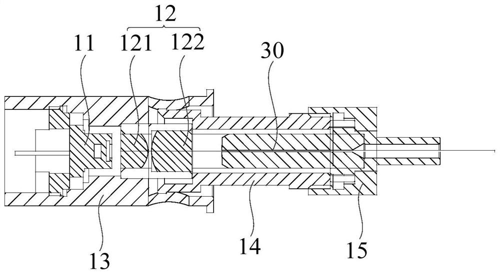
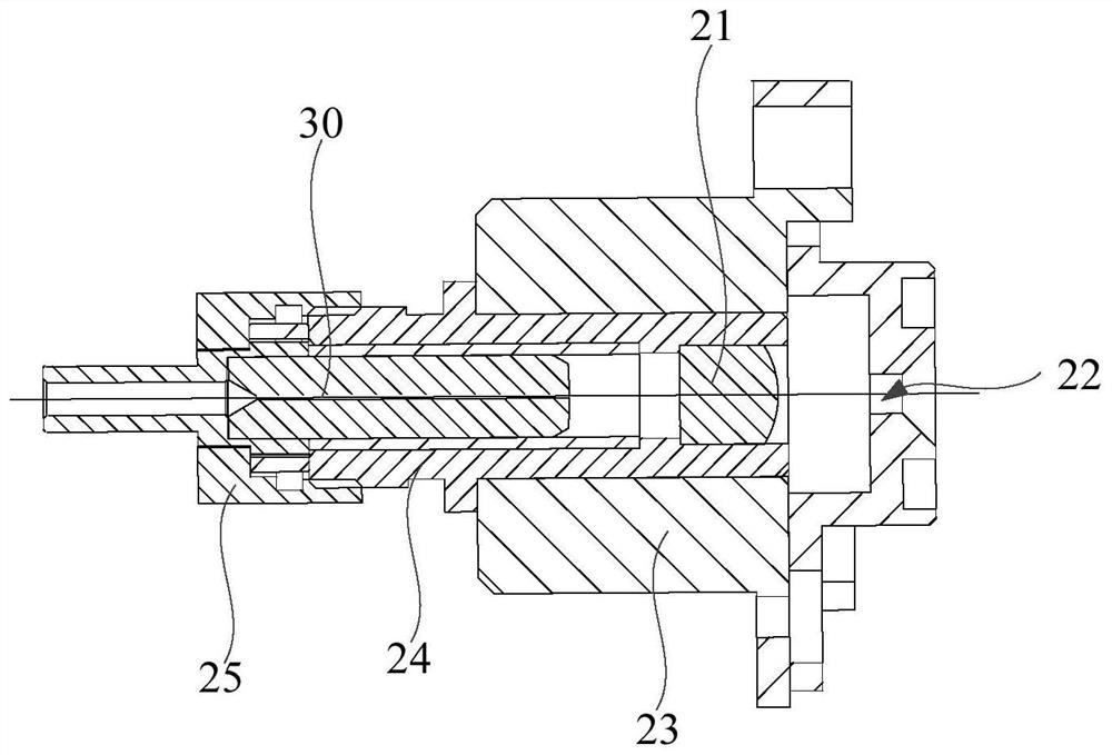
The invention relates to a marking and positioning device and an exposure machine. The marking and positioning device comprises a light source head, a marking head and an optical fiber. The light source head comprises a light source and a coupling lens. The marking head comprises a collimating lens. The light incident end of the optical fiber is connected with the light source head. The light outlet end of the optical fiber is connected with the marking head. A light beam emitted by the light source head is output after passing through the coupling lens, the optical fiber and the collimating lens in sequence. By means of the scheme, the marking and positioning device can realize high-precision marking and positioning, and is simple in overall structure, low in cost, stable in performance and high in cost performance.

Description

technical field [0001] The invention relates to the technical field of visual recognition, in particular to a marking positioning device and an exposure machine. Background technique [0002] With the improvement of integrated circuit integration and the progress of installation technology, the requirements for the production of PCB boards are also getting higher and higher. There are many manufacturing processes and complex processes for PCB boards. One of the processes is to transfer the designed circuit layout to the PCB board to form a PCB circuit diagram. This process is the exposure technology, and the main equipment used is the exposure machine. Generally, the PCB board adopts a multi-layer structure, which requires multiple exposures, and precise positioning is required before each exposure. This process requires a marking positioning device. Whether the marking points are clear, reliable and stable will directly affect the manufacturing accuracy and efficiency of P...

Claims


Application Information

Patent Timeline
IPC IPC(8): B23K26/362G03F7/20
CPCB23K26/362G03F7/20
Inventor 李永忠
Owner ZHONGSHAN AISCENT TECH
Learn More