Shearing equipment based on chip manufacturing
A technology of shearing equipment and chips, applied in the direction of manufacturing tools, stone processing equipment, fine working devices, etc., can solve the problems of easily damaged chips, and achieve the effect of preventing chapping
- Summary
- Abstract
- Description
- Claims
- Application Information
AI Technical Summary
Problems solved by technology
Method used
Image

Examples
Embodiment 1
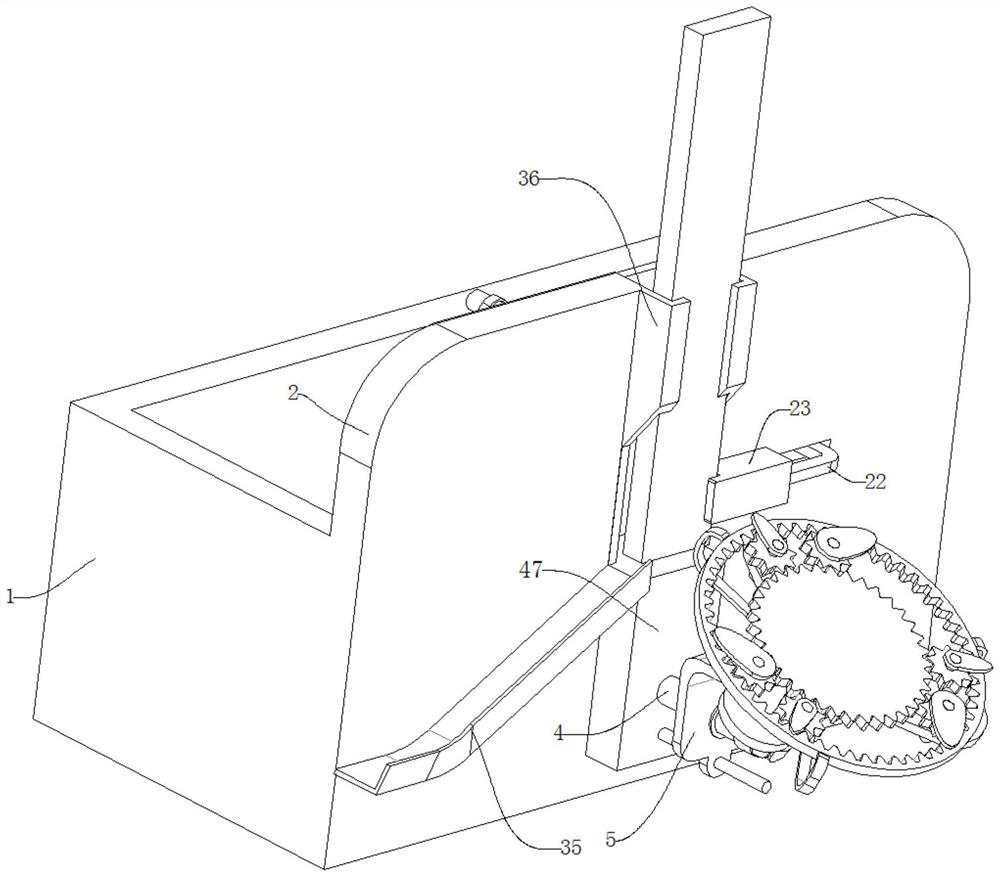
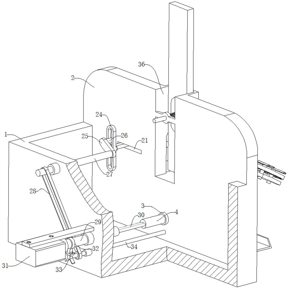
[0027] refer to Figure 1-9 , a shearing device based on chip manufacturing, comprising a box body 1, the box body 1 includes a front baffle 2, and a first through hole 3 is horizontally opened on the front baffle 2, and a slidable installation in the first through hole 3 There is a first tube shaft 4, and the first tube shaft 4 is used to drive a cutting device to cut chips;
[0028] The cutting device includes an L-shaped bent plate 5, the bottom of the bent plate 5 is horizontally provided with a second through hole 6, the top of the bent plate 5 is provided with a notch 12, and one end of the first pipe shaft 4 is slidably installed in the second through hole 6, A second short shaft 37 is rotatably installed on the side wall of the notch 12, and a rotating structure for preventing the rotation of the second short shaft 37 is installed on one end of the second short shaft 37. The rotating structure includes a worm wheel 38, a worm screw 40, a screw rod 41 and Tighten the n...
Embodiment 2
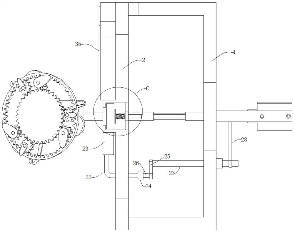
[0040] In order to reduce the time taken by chip loading and unloading, on the basis of the above-mentioned embodiment 1, this implementation is equipped with a loading and unloading structure for chip feeding and discharging on the box body 1, such as Figure 1-3 As shown, the loading and unloading structure includes an L-shaped curved bar 22, a slide block 23, a return frame 24, a connecting plate 25, a slide bar 26, a drive shaft 27, a belt 28, a discharge slide 35, a feed slide 36 and Limiting platform 47, feeding slideway 36 is vertically fixed on the top of front baffle plate 2, and limiting platform 47 is fixed on the casing 1 outer wall between feeding slideway 36 bottoms and first through hole 3, limit The bit platform 47 is located directly below the feeding chute 36, a chute 21 is provided on one side of the front baffle 2, the curved rod 22 is slidably connected in the chute 21, and the slider 23 is fixed on the curved rod 22 close to the feeding material. On one e...
Embodiment 3
[0042] In the above-mentioned embodiment 2, if the thickness of the chip in the feed chute 36 is insufficient, the pressure will shake in the feed chute 36 during the cutting process, and the lack of stability will cause chipping or cracking when the chip is cut. To prevent the above-mentioned situation, the present embodiment is provided with a supporting structure for improving stability during chip cutting in the feed slideway 36, such as Figure 3-9 As shown, the support structure includes a slide tube 43, a guide rod 44, a pressing plate 45 and a compression spring 46. The slide tube 43 is fixedly connected to the feeding slide 36, the guide rod 44 is slidably connected in the slide tube 43, and the pressing plate 45 is fixed. Connected to the end of the guide rod 44 located in the feed slideway 36, the compression spring 46 is sleeved on the guide rod 44 between the pressing plate 45 and the slide pipe 43, and the pressing plate 45 is pressed by the compression spring 46,...
PUM
 Abstract
Description
Claims
Application Information
 - R&D Engineer
- R&D Manager
- IP Professional
- Industry Leading Data Capabilities
- Powerful AI technology
- Patent DNA Extraction
Browse by: Latest US Patents, China's latest patents, Technical Efficacy Thesaurus, Application Domain, Technology Topic.
© 2024 PatSnap. All rights reserved.Legal|Privacy policy|Modern Slavery Act Transparency Statement|Sitemap