Check patentability & draft patents in minutes with Patsnap Eureka AI!

Device and method for separating reaction-generated gases from propane dehydrogenation to propylene

A propane dehydrogenation and separation device technology, applied in the chemical industry, can solve the problems of difficult compression and high energy consumption of refrigerants, etc.

Active Publication Date: 2020-11-06
SINOPEC ENG +1
View PDF10 Cites 0 Cited by
  • Summary
  • Abstract
  • Description
  • Claims
  • Application Information

AI Technical Summary

Problems solved by technology

Since the gas generated by the propane dehydrogenation reaction contains a large amount of hydrogen, the use of low-temperature expansion refrigeration is actually the reaction product gas compressor to compress the hydrogen expansion refrigeration. Due to the small molecular weight of hydrogen, it is difficult to compress, so it is used as -100 ℃ to -160 ℃ Refrigerant consumes a lot of energy

Method used


Image

  • Device and method for separating reaction-generated gases from propane dehydrogenation to propylene
  • Device and method for separating reaction-generated gases from propane dehydrogenation to propylene
  • Device and method for separating reaction-generated gases from propane dehydrogenation to propylene

Examples


Embodiment 1

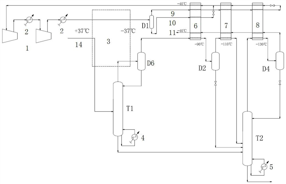
[0045] use as figure 2 Shown is a separation device for generating gas from propane dehydrogenation to propylene reaction, the separation device includes: mixed refrigerant compressor 1, propylene refrigeration system 3, light and heavy refrigerant liquid separation tank D1, primary cold box 6, and secondary cold box 7 , three-stage cold box 8, first liquid separation tank D2, third liquid separation tank D3, pre-demethanizer T1, demethanizer T2; mixed refrigerant compressor 1 is sequentially separated from propylene refrigeration system 3, light and heavy refrigerants The tank D1 is connected; the top of the tank D1 is equipped with a light refrigerant pipeline, and the bottom of the tank is equipped with a heavy refrigerant pipeline. The light refrigerant pipeline is connected with the primary cold box 6, the secondary cold box 7, and the third cold box 8, and then reversely connected with the third-stage cold box 8, the second-level cold box 7, the first-level cold box 6 a...

Embodiment 2

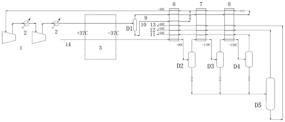
[0052] use as image 3 Shown is a separation device for generating gas from propane dehydrogenation to propylene reaction, the separation device includes: mixed refrigerant compressor 1, propylene refrigeration system 3, light and heavy refrigerant liquid separation tank D1, primary cold box 6, and secondary cold box 7 , three-stage cold box 8, the first liquid separation tank D2, the second liquid separation tank D3 and the third liquid separation tank D4; the mixed refrigerant compressor 1 is connected with the propylene refrigeration system 1 and the light and heavy refrigerant liquid separation tank D1 in turn; The top of the light and heavy refrigerant separation tank D1 is equipped with a light refrigerant pipeline, and the bottom of the tank is equipped with a heavy refrigerant pipeline. The light refrigerant pipeline is connected with the first-level cold box 6, the second-level cold box 7, and the third-level cold box 8 in sequence. Reversely connected with the third-s...


PUM


Abstract

The inventio belongs to the field of chemical engineering and discloses a device and method for separating reaction-generated gases from propane dehydrogenation to propylene. The separating device comprises a mixed refrigerant compressor, a propylene refrigerating system, a light and heavy refrigerant liquid separation container and a cold box sequence comprising one or more cold boxes. The mixedrefrigerant compressor, the propylene refrigerating system, the light and heavy refrigerant liquid separation container and the cold box sequence are connected in sequence, and an enclosed loop is formed. According to the technical scheme provided by the separating device, the reaction-generated gases do not need throttling expansion refrigeration themselves; only by adjusting the reasonable refrigerant proportion and operating parameters, heat exchange is conducted on the reaction-generated gases and the mixed refrigerants; the temperature level between minus 160 DEG C and minus 40 DEG C canbe achieved finally; and under the premise that the equipment investment is reduced, the purpose of recycling propylene products fully is achieved.

Description

technical field [0001] The invention belongs to the field of chemical industry, and more specifically relates to a separation device and separation method for producing gas from the reaction of propane dehydrogenation to propylene. Background technique [0002] Propylene is an important petrochemical basic raw material whose total output is second only to ethylene. The downstream products mainly include polypropylene, acrylonitrile, propylene oxide, cumene / phenol / acetone / bisphenol A, acrylic acid and esters, epichlorohydrin . About 70% of the world's propylene comes from co-products of steam cracking units and by-products of catalytic cracking units in refineries. With the rapid growth of demand for downstream products such as polypropylene and the increase in the proportion of new ethylene production plants using ethane as raw material, the supply of propylene resources is gradually showing a tense situation. In 2014, the global production capacity of polymer grade propyl...

Claims


Application Information

Patent Timeline
Patent Type & Authority Applications(China)
IPC IPC(8): F25J3/02
CPCF25J3/0242F25J3/0252F25J3/0295F25J2270/66F25J3/0219F25J2200/74F25J2270/60F25J2270/12F25J2270/18F25J2210/12F25J2205/02F25J3/062F25J3/0645F25J3/0655F25J2215/64F25J2270/04
Inventor 孙丽丽彭勃李广华
Owner SINOPEC ENG
Features
  • R&D
  • Intellectual Property
  • Life Sciences
  • Materials
  • Tech Scout
  • Unparalleled Data Quality
  • Higher Quality Content
  • 60% Fewer Hallucinations
Learn More