Eureka AIR delivers breakthrough ideas for toughest innovation challenges, trusted by R&D personnel around the world.

Three-dimensional imaging and reconstruction method of millimeter wave cylindrical surface holographic imaging system

A three-dimensional imaging and holographic imaging technology, which is applied in radio wave measurement systems, radio wave reflection/re-radiation, utilization of re-radiation, etc., can solve the problem of deteriorating system imaging quality, difficult to achieve three-dimensional reconstruction of targets, and difficult to extract three-dimensional imaging results. Point cloud distribution data and other issues

Active Publication Date: 2020-11-06
NAT UNIV OF DEFENSE TECH
View PDF7 Cites 4 Cited by
  • Summary
  • Abstract
  • Description
  • Claims
  • Application Information

AI Technical Summary

Problems solved by technology

However, as the angle increases, the spatial spectrum domain of the Cartesian coordinate system gradually becomes circular. At this time, the accuracy of interpolation and NUFFT conversion will be affected to a certain extent, and it is easy to introduce non-ideal DC components and other frequency components, which will further deteriorate The imaging quality of the system; therefore, in order to ensure the accuracy of interpolation and NUFFT, the density of interpolation in the spatial wavenumber spectral domain is high, which will result in a large horizontal imaging range, reduce the operating efficiency of the algorithm, and introduce uninteresting non-target imaging area
In addition, the 3D imaging results of the Cartesian coordinate algorithm are not easy to extract the point cloud distribution data of the target surface, and it is difficult to realize the 3D reconstruction of the target

Method used


Image

  • Three-dimensional imaging and reconstruction method of millimeter wave cylindrical surface holographic imaging system
  • Three-dimensional imaging and reconstruction method of millimeter wave cylindrical surface holographic imaging system
  • Three-dimensional imaging and reconstruction method of millimeter wave cylindrical surface holographic imaging system

Examples


Embodiment Construction

[0061] In order to make the purpose, technical solution and advantages of the present application clearer, the present application will be further described in detail below in conjunction with the accompanying drawings and embodiments. It should be understood that the specific embodiments described here are only used to explain the present application, and are not intended to limit the present application.

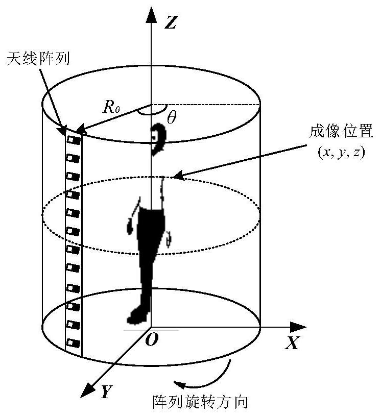
[0062] A three-dimensional imaging and reconstruction method of a millimeter-wave cylindrical holographic imaging system provided by this application can be applied to such as figure 1 shown in the application environment. The system sets the millimeter-wave radar and its receiving antenna array along the vertical direction. The array can scan 360 degrees around the central axis of the device, and receive the scattered echoes of the detected target inside the cylinder in real time during the scanning process.

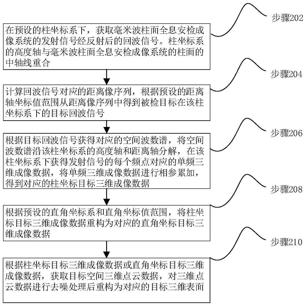
[0063] In one embodiment, such as figure 2 As shown, a thre...


PUM


Abstract

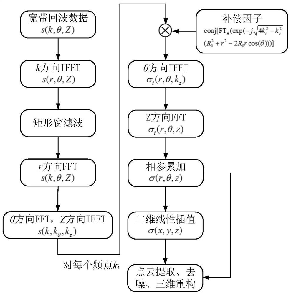
The invention relates to a three-dimensional imaging and reconstruction method of a millimeter wave cylindrical surface holographic imaging system. The method comprises the steps of obtaining an echosignal under a cylindrical coordinate system; obtaining an echo signal of a detected target and a corresponding spatial wave number spectrum from the range profile sequence of the echo signal; decomposing the spatial wave number spectrum along a height axis and a distance axis to obtain single-frequency three-dimensional imaging data of each frequency point of the transmitting signal under the cylindrical coordinate system; obtaining cylindrical coordinate target three-dimensional imaging data through coherent accumulation and reconstructing into rectangular coordinate target three-dimensionalimaging data; and obtaining three-dimensional point cloud data of the target three-dimensional imaging data under cylindrical coordinates or rectangular coordinates and reconstructing into a corresponding target three-dimensional surface. According to the method, the three-dimensional imaging result is directly obtained under the cylindrical coordinate system, the precision loss caused by the spatial wave number spectral domain conversion operation from the cylindrical coordinate to the rectangular coordinate is avoided, and the omnibearing high-quality imaging result of the target can be obtained at one time; the imaging range can be set, and the imaging efficiency is improved.

Description

technical field [0001] The present application relates to the fields of radar signal processing technology and radar imaging technology, in particular to a three-dimensional imaging and reconstruction method of a millimeter-wave cylindrical holographic imaging system. Background technique [0002] Millimeter waves generally refer to electromagnetic waves with a frequency between 30GHz and 300GHz (corresponding to a wavelength of 1mm-10mm). Compared with microwave and lower-frequency electromagnetic waves, millimeter-wave radar has the characteristics of higher carrier frequency, shorter wavelength, and easier to provide large bandwidth, so its imaging results have higher distance resolution and azimuth resolution. Inspection, non-destructive detection and other fields have great application prospects. The currently used millimeter-wave imaging systems can be mainly divided into two categories according to their geometric structures, namely planar holographic imaging systems...

Claims


Application Information

Patent Timeline
Patent Type & Authority Applications(China)
IPC IPC(8): G01S13/89G01S13/88
CPCG01S13/89G01S13/887
Inventor 杨琪张野江新瑞邓彬王宏强
Owner NAT UNIV OF DEFENSE TECH
Why Eureka
Eureka Blog
Learn More