
Multi-stage depressed collector with deflection magnetic field

A deflection magnetic field and collector technology, which is applied to collectors, discharge tubes, and electrical components of time-of-flight electron tubes, can solve the problems of electron injection backflow and low heat dissipation efficiency, and achieve simple structure, easy processing, and collection high efficiency effect

Active Publication Date: 2020-11-10
UNIV OF ELECTRONICS SCI & TECH OF CHINA
View PDF4 Cites 0 Cited by
  • Summary
  • Abstract
  • Description
  • Claims
  • Application Information

AI Technical Summary

Problems solved by technology

[0004] Aiming at the problems of electron injection backflow and low heat dissipation efficiency in the existing step-down collector in the background technology, the purpose of the present invention is to provide a multi-stage step-down collector with deflection magnetic field

Method used


Image

  • Multi-stage depressed collector with deflection magnetic field
  • Multi-stage depressed collector with deflection magnetic field
  • Multi-stage depressed collector with deflection magnetic field

Examples


Embodiment Construction

[0029] In order to make the purpose, technical solution and advantages of the present invention clearer, the present invention will be further described in detail below in conjunction with the implementation methods and accompanying drawings.

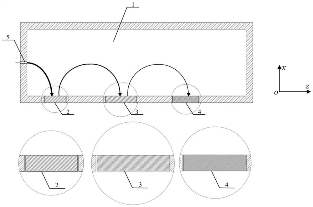
[0030] figure 1 It is a schematic diagram of the working principle of the cross section of the present invention perpendicular to the direction of the inlet electron injection channel. After the interaction of the slow wave structure of the traveling wave tube, the remaining electrons decelerate through the electron beam channel in the first-stage cavity electrode and enter the rectangular cavity. Under the action of the magnetic field, they pass through the second-stage blade electrode and the third-stage blade. The electrodes and the fourth-stage blade electrodes are respectively connected to power supplies of different voltages, and the collected current is fed back to the power supply for reuse. In addition, due to the action of th...


PUM


Abstract

The invention provides a multistage depressed collector with a deflection magnetic field, and belongs to the technical field of vacuum electronics. According to the collector, the whole collector is arranged in the deflection magnetic field perpendicular to an incident electron direction, so that most electrons hit the same side of the collector under the action of the deflection magnetic field, and the heat dissipation efficiency of the collector can be effectively improved. In addition, the device has the advantages of being simple in structure, easy to machine, high in collection efficiencyand free of backflow. The collector with the three-stage blades is used for collecting the residual electrons after interaction of the 220GHz strip beam traveling wave tubes, the collection efficiency is as high as 98.86%, and most of the electrons hit the side wall of the collector.

Description

technical field [0001] The invention belongs to the technical field of vacuum electronics, and in particular relates to a multi-stage voltage-reducing collector, which collects electron residual energy under the action of a deflection magnetic field. Background technique [0002] As a final power amplifier, traveling wave tubes are widely used in electronic equipment such as radar, electronic warfare, satellite communication, and precision guidance. An important factor to measure the quality of the traveling wave tube is the efficiency of the traveling wave tube. There are generally two ways to improve the efficiency of traveling wave tubes: one is to increase the electronic efficiency of the interaction between electrons and slow wave structures to improve the overall tube efficiency of traveling wave tubes; the other is to use step-down collectors to recover and slow wave structures The energy of the remaining electrons after the interaction, thereby improving the efficie...

Claims


Application Information

Patent Timeline
Patent Type & Authority Applications(China)
IPC IPC(8): H01J23/027H01J23/033H01J25/34
CPCH01J23/0275H01J23/033H01J25/34H01J2223/0275H01J2223/033
Inventor 段兆云麦尔丹·吾拉木吕志方江胜坤王战亮巩华荣宫玉彬
Owner UNIV OF ELECTRONICS SCI & TECH OF CHINA
Learn More