Super-capacitor energy storage device for assisting frequency modulation and control method

A technology of capacitive energy storage and auxiliary frequency modulation, which is applied in circuit devices, battery circuit devices, collectors, etc., can solve the problems of increasing the number of switching devices and circuit complexity, high switching loss, and current waveform distortion, etc., to facilitate integration Design, simplify the voltage equalization process, and reduce the effect of switching loss

Active Publication Date: 2020-11-10
STATE GRID JIANGSU ELECTRIC POWER CO ELECTRIC POWER RES INST +2
View PDF2 Cites 7 Cited by
  • Summary
  • Abstract
  • Description
  • Claims
  • Application Information

AI Technical Summary

Problems solved by technology

Considering that the output current of traditional energy storage converters is already sufficient to meet the harmonic requirements shown in GB 14549-93 "Power Quality Harmonics of Public Power Grids", the project to further increase the level number of chain-link converters and reduce output waveform distortion Insignificant, and would significantly increase the number of switching devices and circuit complexity
[0004] In terms of supercapacitor product selection, traditional energy storage converters generally use the same supercapacitor product, which makes it difficult to balance device performance and energy storage costs. The capacitor sub-module is added with a voltage equalizing ring to achieve charging and discharging balance of the super capacitor sub-module. The control structure is complicated, and the carrier phase relationship needs to be calculated in real time to meet the harmonic requirements of the power grid.
The existing level-approximation modulation does not consider the internal resistance voltage drop at the instant when the supercapacitor sub-module is connected, which may cause current waveform distortion when it is applied to low-voltage large-capacity energy storage and has a large number of sub-modules

Method used


Image

  • Super-capacitor energy storage device for assisting frequency modulation and control method
  • Super-capacitor energy storage device for assisting frequency modulation and control method
  • Super-capacitor energy storage device for assisting frequency modulation and control method

Examples


Embodiment Construction

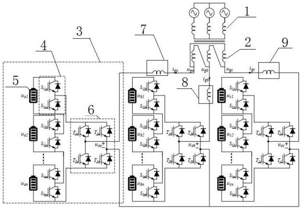
[0031] Such as figure 1 , the present invention includes 10kV power grid 1, star-delta transformer 2, filter inductance and bridge arm module, wherein the bridge arm module comprises the first bridge arm module 3, the second bridge arm module and the third bridge arm module, and the filter inductance comprises the first bridge arm module A filter inductor 7, a second filter inductor 8 and a third filter inductor 9, the 10kV grid 1 is electrically connected to the input terminal of the star-delta transformer 2, the output terminal of the star-delta transformer 2 is electrically connected to the filter inductor, and the first filter inductor 7 It is electrically connected to the input end of the first bridge arm module 3, the second filter inductor 8 is electrically connected to the input end of the second bridge arm module, the third filter inductor 9 is electrically connected to the input end of the third bridge arm module, and the first bridge arm module The output terminal o...


PUM


Abstract

The invention discloses a super capacitor energy storage device for assisting frequency modulation, and the device comprises a power grid, a three-phase transformer, a filter inductor and a bridge armmodule; the bridge arm module comprises a first bridge arm module, a second bridge arm module and a third bridge arm module, and the filter inductor comprises a first filter inductor, a second filterinductor and a third filter inductor. The invention further discloses a control method of the super-capacitor energy storage device for assisting frequency modulation. According to the super-capacitor energy storage device, the online switching and replacement of the super-capacitor sub-modules are achieved, and energy storage and overall integrated design of the converter are facilitated; the switching loss is reduced, the voltage-sharing process of the super-capacitor sub-module is simplified, and parameter setting of a large number of voltage-sharing loops is avoided; and a large number ofswitching devices are saved on the basis of ensuring that output waveforms meet power grid harmonic requirements.

Description

technical field [0001] The invention relates to the field of energy storage control, in particular to a supercapacitor energy storage device and a control method for assisting frequency modulation. Background technique [0002] As a fast and controllable power source, the energy storage device can effectively improve the transient performance of the frequency modulation unit and keep the frequency of the regional power grid stable. Among them, the supercapacitor stores the charge in a physical way, with faster charging and discharging speed, higher efficiency and low safety risk , The cycle life is up to 500,000 times, and no maintenance is required during the life cycle. [0003] However, the integration of supercapacitors is difficult, the internal voltage and current equalization measures of high-voltage and large-capacity modules are complicated, and the centralized DC bus power supply structure of traditional energy storage converters brings inconvenience to the applica...

Claims


Application Information

Patent Timeline
Patent Type & Authority Applications(China)
IPC IPC(8): H02J3/32H02J7/34H02J3/24
CPCH02J3/32H02J7/345H02J3/241
Inventor 张军付慧史明明袁宇波杨景刚李双伟张宸宇费骏韬
Owner STATE GRID JIANGSU ELECTRIC POWER CO ELECTRIC POWER RES INST
Why Eureka
Try Eureka