
Cooling garment suitable for electric field environment

An electric field and environment technology, applied in the field of cooling clothing, can solve the problems of live work scenes that are not suitable for shielding clothing, poor ventilation of shielding clothing, difficult air flow, etc. masking effect

Pending Publication Date: 2020-11-13
国网浙江省电力有限公司双创中心 +2
View PDF2 Cites 1 Cited by
  • Summary
  • Abstract
  • Description
  • Claims
  • Application Information

AI Technical Summary

Problems solved by technology

[0003] Among them, Chinese utility model patent CN208510118U discloses a cooling suit, including insulation layer, lining, Velcro I, Velcro II, liquid circulation pipeline, heat exchange tube, temperature sensor, phase change material, pump, heat exchange tube Surrounded by the phase change material, the phase change material is embedded and fixed on the inner lining, and the cooling capacity of the material is circulated to various parts of the clothes through the commutation liquid inside the liquid circulation pipeline to achieve the purpose of cooling, but the liquid commutation is easy to cause Leakage, which brings potential safety hazards, not suitable for live working environment
[0004] In addition, Chinese invention patent CN109380782A discloses a cooling garment, which includes a clothing body and a cooling block arranged on the clothing body. The cooling block includes a unidirectional moisture-conducting layer, a hydrogel functional layer, and a phase The change material layer and the waterproof and moisture-permeable layer achieve the purpose of cooling through the evaporation and heat absorption of water in the hydrogel functional layer and the phase change heat absorption of the phase change material layer, but the air permeability of the shielding suit is very poor, the air is not easy to flow, and the water Parts are difficult to evaporate, not suitable for live working scenes wearing shielding clothing

Method used


Image

  • Cooling garment suitable for electric field environment
  • Cooling garment suitable for electric field environment
  • Cooling garment suitable for electric field environment

Examples


Embodiment 1

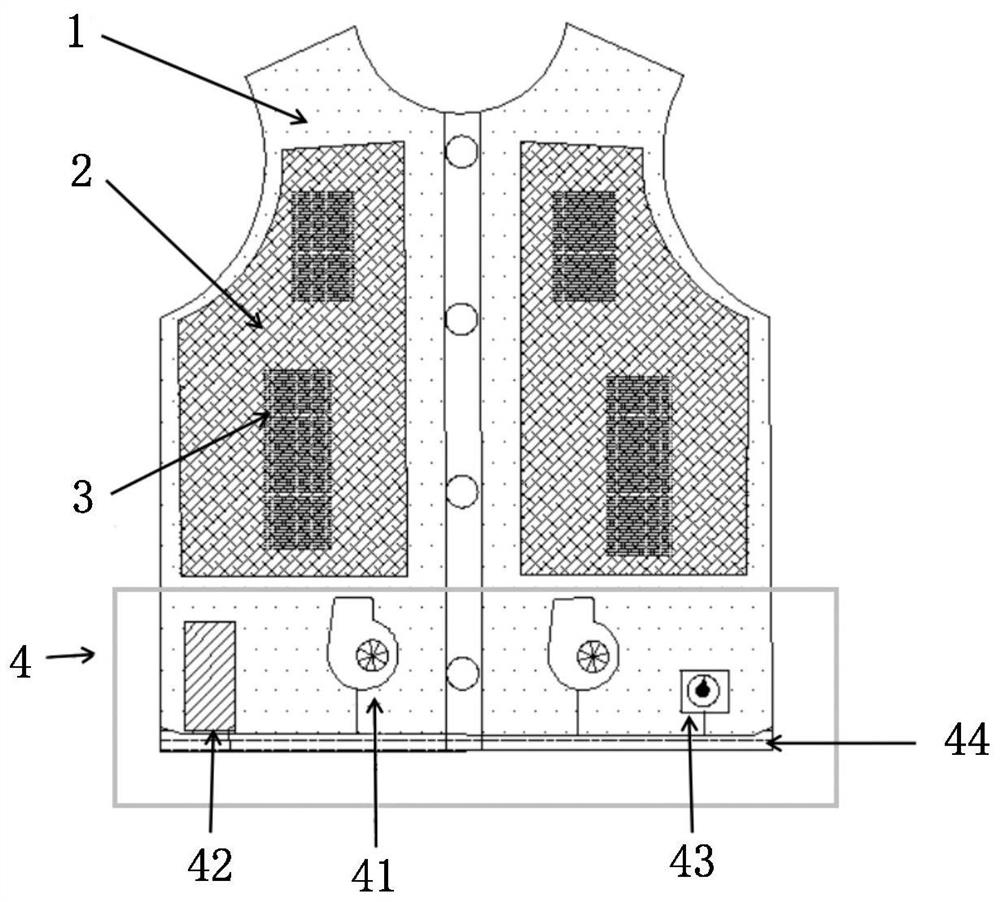
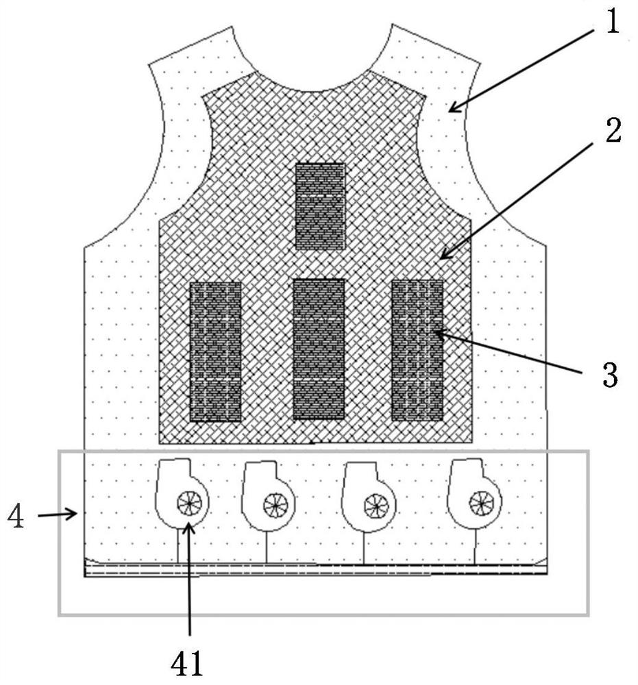
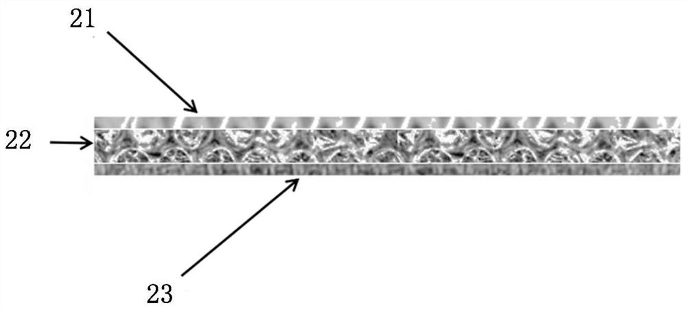
[0029] like Figure 1 to Figure 3 As mentioned above, this embodiment shows a cooling suit suitable for an electric field environment, including a garment body 1, a superabsorbent inner lining 2, a cold source module 3 and a fan module 4, wherein the garment body 1 is used to shield the external electric field, The superabsorbent lining 2 is arranged inside the garment body 1, the cold source module 3 is arranged between the garment body 1 and the superabsorbent lining 2, and the fan module 4 is arranged below the superabsorbent lining 2, The fan module 4 is used to deliver cold air provided by the cold source module 3 .

[0030] This embodiment includes a garment body 1, a superabsorbent inner lining 2, a cold source module 3 and a fan module 4, wherein the cold source module 3 releases cold air for cooling, and the fan module 4 forms an air flow in the superabsorbent inner lining 2 , to deliver the cold air provided by the cold source module 3 to other parts, thereby coolin...


PUM


Abstract

The invention provides a cooling garment suitable for an electric field environment. The cooling garment comprises a garment body, a super-absorbent lining, a cold source module and a fan module. Specifically, the garment body is used for shielding an external electric field, the super-absorbent lining is arranged on the inner side of the garment body, the cold source module is arranged between the garment body and the super-absorbent lining, the fan module is arranged below the super-absorbent lining, and the fan module is used for conveying cold air provided by the cold source module. The cooling garment has the advantages that: the risk of liquid leakage is avoided, the cooling performance is good, and the cooling garment is suitable for workers who wear shielding garments and are in hot-line work scenes.

Description

【Technical field】 [0001] The invention relates to a cooling suit suitable for an electric field environment, which belongs to the technical field of personal protective equipment. 【Background technique】 [0002] During the live working process of high-voltage / ultra-high-voltage overhead transmission lines, operators must wear heavy shielding clothing to ensure safe operation. The shielding clothing is made of metal fiber and flame-retardant fiber blended. It is a protective clothing for special operations with electric field shielding and flame-retardant properties. In order to ensure the shielding efficiency, the shielding clothing fabric must have a certain thickness and compactness, resulting in poor air permeability of the clothing. Difference. Moreover, the shielding suit cannot be in direct contact with the human body, and underwear is required inside the suit. When working live on an outdoor unshielded transmission tower, the high temperature of the environment and t...

Claims


Application Information

Patent Timeline
Patent Type & Authority Applications(China)
IPC IPC(8): A41D13/005A41D13/008A41D31/08A41D31/02A41D27/00A41D31/12
CPCA41D13/0053A41D13/008A41D27/00A41D31/02A41D31/12
Inventor 虞驰方玉群张波王斌秦威南赵凯美朱凯江川张庭瑞
Owner 国网浙江省电力有限公司双创中心
Learn More