

Double-layer embolectomy device
A double-layer, inner-layer technology, applied in the field of medical devices, can solve problems such as small thrombus falling off, vessel wall damage, dissection, and secondary embolism
- Summary
- Abstract
- Description
- Claims
- Application Information
AI Technical Summary
Problems solved by technology
Method used
Image

Examples
Embodiment 2
[0048] This embodiment is a modification made on the basis of Embodiment 1. The difference between this embodiment and Embodiment 1 is:
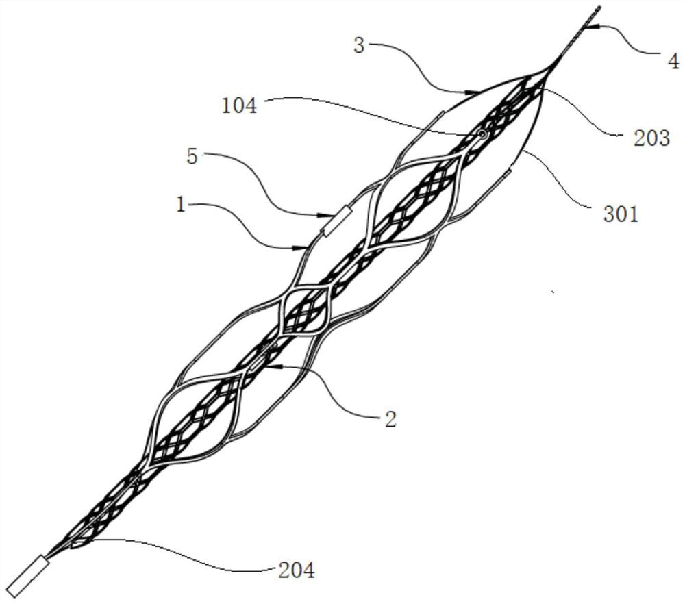
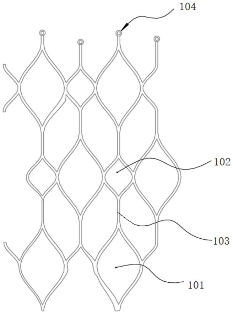
[0049] The weaving mode of the blockade net structure 3 in the present embodiment and the grid shape of the blockade net structure 3 that form are different from embodiment 1, refer to Figure 5 The end of the outer layer net 1 is provided with four outer layer threading holes 104 of A, B, C, and D, and the far end of the inner layer net 2 is provided with four inner layer threading holes 203 of a, b, c, and d. A silk thread 301, whose connection weaving mode is: A-b-C-d-A and a-B-c-D-a, there is a cross when the silk thread 301 connects the outer layer threading hole 104 and the inner layer threading hole 203, and the blockade network structure 3 formed is as Figure 5 The overlapping petal shapes shown in . Of course, in other embodiments, the number of silk threads 301 used is not limited, and the way the silk threads 301 are braided and...
Embodiment 3
[0052] This embodiment is a modification made on the basis of Embodiment 1. The difference between this embodiment and Embodiment 1 is:
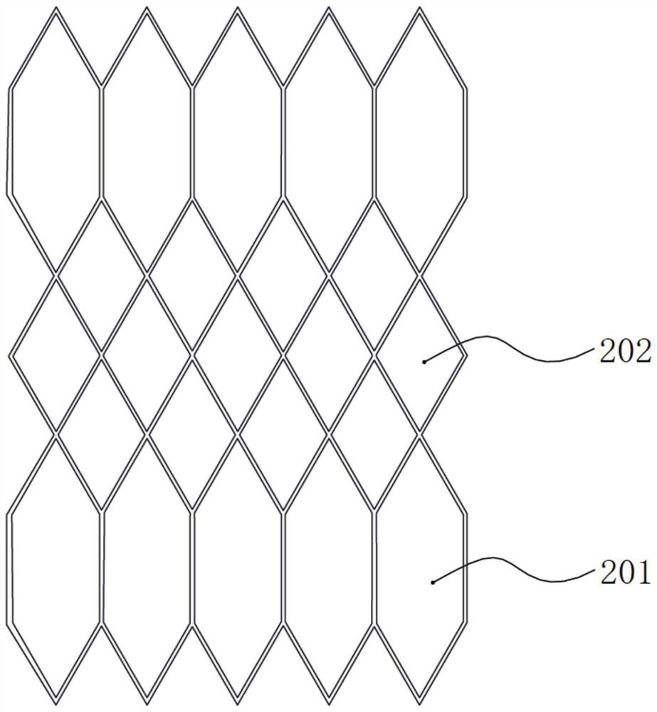
[0053] The inner grid unit is at least a quadrilateral unit. In this embodiment, refer to Image 6 , the preferred inner grid unit is an irregular polygon, which can increase the bending radius of the inner grid 2 and make it easier for the inner grid 2 to pass through some extremely curved blood vessels.
[0054] For other structures and connection methods of the double-layer thrombectomy device, refer to Embodiment 1, which will not be repeated here.
Embodiment 4
[0056] This embodiment is a modification made on the basis of Embodiment 1. The difference between this embodiment and Embodiment 1 is:
[0057] In this example, see Figure 7 , the outer mesh 1 comprises a first outer mesh unit 101 and a second outer mesh unit 102, along the direction from the proximal end to the far end of the outer mesh 1, the first outer mesh unit 101 and the second outer mesh The grid units 102 are arranged at intervals; and the first outer grid unit 101 is connected to the second outer grid through a connecting line 103; along the circumferential direction of the outer net 1, adjacent columns are connected to each other ; Along the circumferential direction of the outer mesh 1, the first outer mesh unit 101 and the second outer mesh unit 102 are connected between adjacent columns.
[0058] In this example, see Figure 7 , along the direction from the proximal end to the distal end of the outer layer mesh 1, preferably part of the connection line 103 be...
PUM
 Abstract
Description
Claims
Application Information