Microparticle machine

A technology of particle and machine base, which is applied in the field of particle machine, can solve the problems of inability to achieve crushing particle size, long drying time, and inability to effectively deal with water separation, so as to improve the effect of crushing and granulation, solve the pain points and difficulties of the industry, and achieve excellent processing capacity. Effect

Pending Publication Date: 2020-11-13
四川眉山中达机械有限公司
View PDF0 Cites 6 Cited by
  • Summary
  • Abstract
  • Description
  • Claims
  • Application Information

AI Technical Summary

Problems solved by technology

The crusher mainly uses the continuously rotating hammer structure to crush the material, and then discharges it through the screen, but it can only process dry materials, and the effect is poor for materials that have not been dried, have high humidity, and have high fiber content. Basically, the required crushing particle size cannot be achieved; when actually processing materials with high humidity, a drying process will be added before processing. Natural drying takes a long time and equipment drying consumes a lot of energy, resulting in high overall processing costs.
Chippers are generally aimed at plant materials such as bamboo and wood. Through the rotating flying knife structure, the continuously fed materials are cut into small pieces and then discharged. However, the size of the sheet materials obtained by conventional structure processing is limited (generally 3-5mm thick) length is 15-20mm), cannot meet the required particle size, and it is also difficult to handle plant materials with high humidity and high fiber content
The inability to effectively deal with plant-based waste materials that are heavy in water and fiber is also a pain point and difficulty in the industry

Method used


Image

  • Microparticle machine
  • Microparticle machine
  • Microparticle machine

Examples


Embodiment

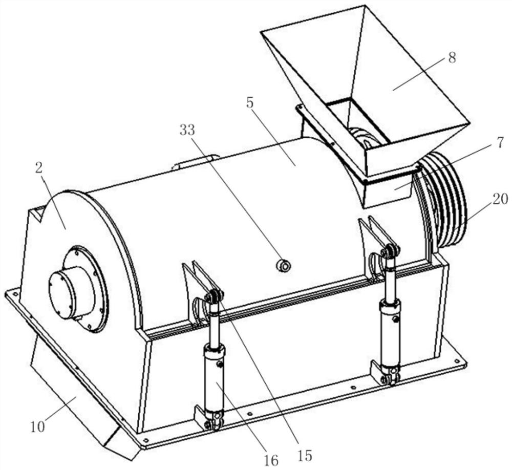
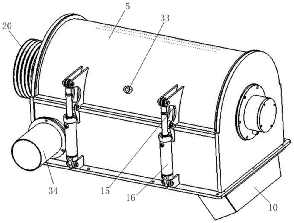
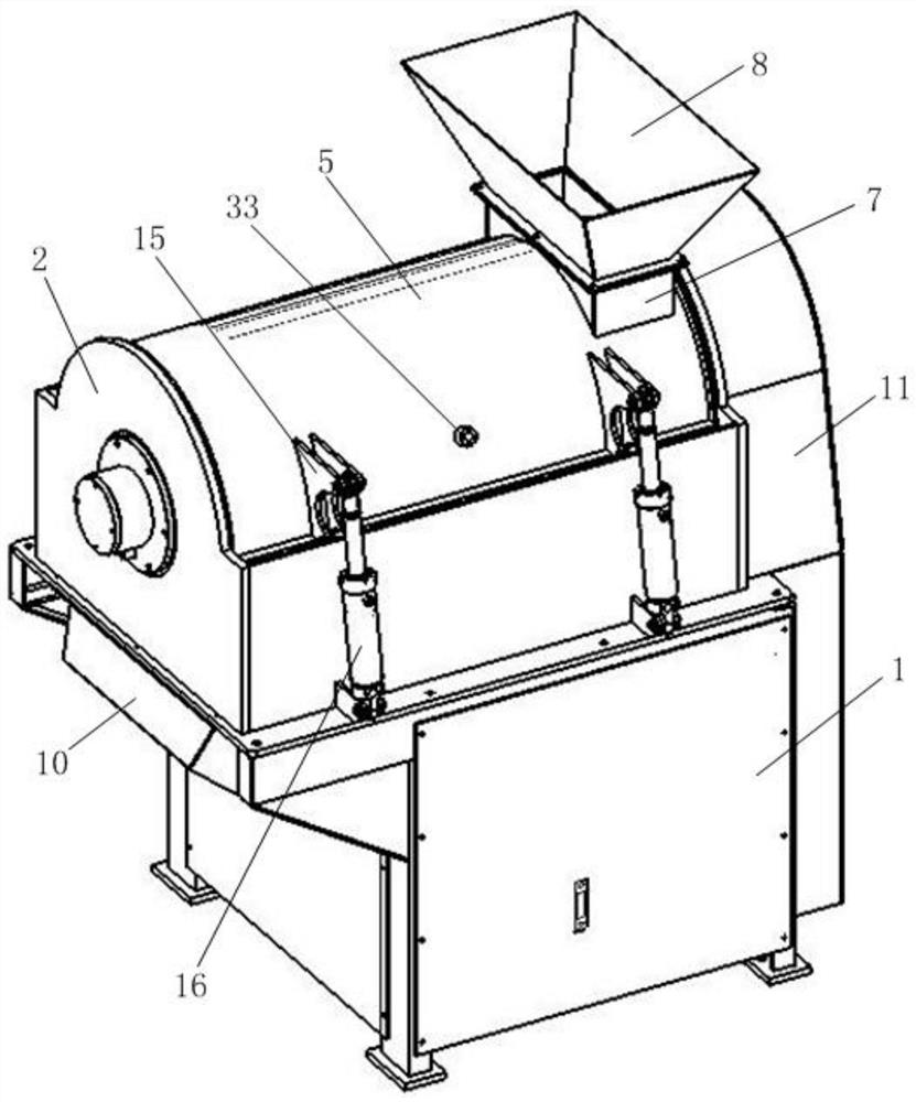
[0045] like Figure 1 to Figure 12 As shown, the particle machine includes a fixedly placed machine base 2, a machine slot 3 that is arranged in the machine base and has a semicircular cross-section, and is opened at the bottom of one end of the machine slot and runs through the discharge port 4 at the bottom of the machine base. A machine cover 5 on the machine base and matched with the machine groove to form a cylindrical crushing space 6, a feed port 7 arranged on the machine base or the machine cover and connected to the other end of the crushing space opposite to the discharge port, The arc-type crushing knife roller 20 that is matched to be arranged in the crushing space and rotatably connected with the base, and the power source 9 for providing operating power for the arc-type crushing knife roll, wherein the base can be used according to the actual application The position is reconfigured with the corresponding lower frame 1; when the feed port is opened on the machine...


PUM


Abstract

The invention discloses a microparticle machine. The microparticle machine comprises a machine base, a machine groove, a discharging hole, a machine cover, a feeding hole, an arc-shaped smashing toolroller and a power source, wherein the machine groove is formed in the machine base; the discharging hole is formed in the bottom of one end of the machine groove; the machine cover is matched with the machine groove to form a smashing space; the feeding hole is formed in the machine base or the machine cover; the arc-shaped smashing tool roller is arranged in the smashing space in a matching way;and the power source is in transmission connection with the arc-shaped smashing tool roller. In the microparticle machine, the arc-shaped smashing tool roller is matched with the smashing space, thecutting smashing manner of materials is changed radically in terms of the smashing principle, a collision-grinding-cutting composite manner substitutes for the original single collision or cutting manner, and the high-speed running state is utilized, so that a superior smashing-granulating effect is achieved in order to meet the demand for materials in the subsequent application field. The microparticle machine particularly has superior processing capability for plant raw materials with heavy moisture and heavy fibers as an industrial pain point.

Description

technical field [0001] The invention relates to the technical field of microparticle machines, in particular to a microparticle machine capable of effectively treating agricultural and forestry wastes with high humidity and high fiber content into tiny particles. Background technique [0002] Environmental protection is one of the most important issues in building an ecological civilization. On the one hand, through relevant policy control, on the other hand, carry out major industry adjustments, promote scientific and technological innovation, and use new technology applications to solve many problems in environmental protection. Among them, prohibiting the burning of agricultural and forestry waste is an important aspect of reducing ambient air pollution. Although relevant policies have been implemented for many years and relevant departments have spent a lot of human and financial resources, the effect is hardly satisfactory, and this situation is likely to continue. [...

Claims


Application Information

Patent Timeline
Patent Type & Authority Applications(China)
IPC IPC(8): B02C18/14B02C18/18B02C18/16
CPCB02C18/0084B02C18/14B02C18/16B02C18/18B02C2201/06
Inventor 李茂华
Owner 四川眉山中达机械有限公司
Why Eureka
Try Eureka