A combined floating anti-wave equipment
A combined and wave-absorbing technology, applied in breakwaters, shore walls, sea area engineering, etc., can solve the problems of flexible structure floating breakwaters with low wave impact resistance, difficulty in meeting rapid maneuvering, deployment, and high ductility design requirements, etc., to achieve The effect of protecting marine ecology, easy to unfold or retract, and easy to reinforce and maintain
- Summary
- Abstract
- Description
- Claims
- Application Information
AI Technical Summary
Problems solved by technology
Method used
Image
Examples
Embodiment 1
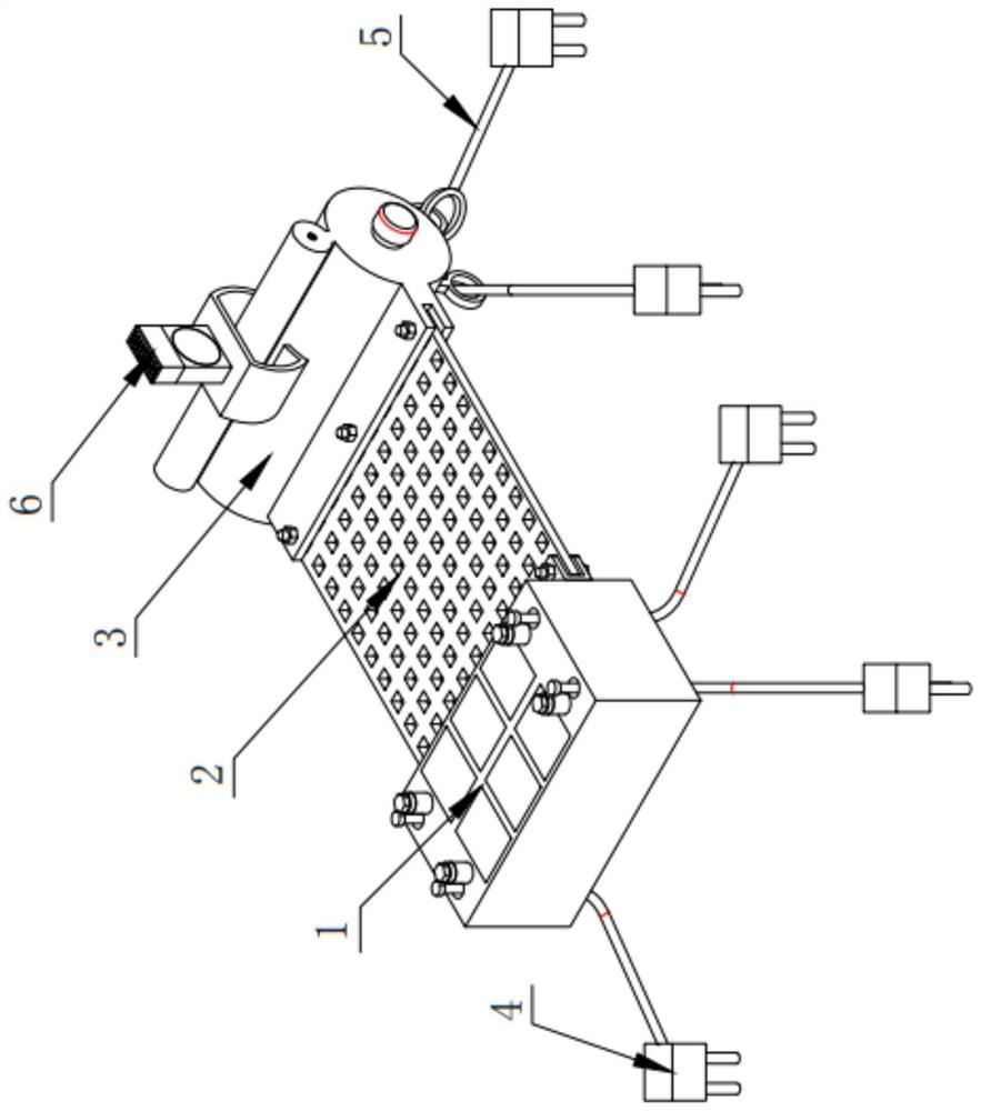
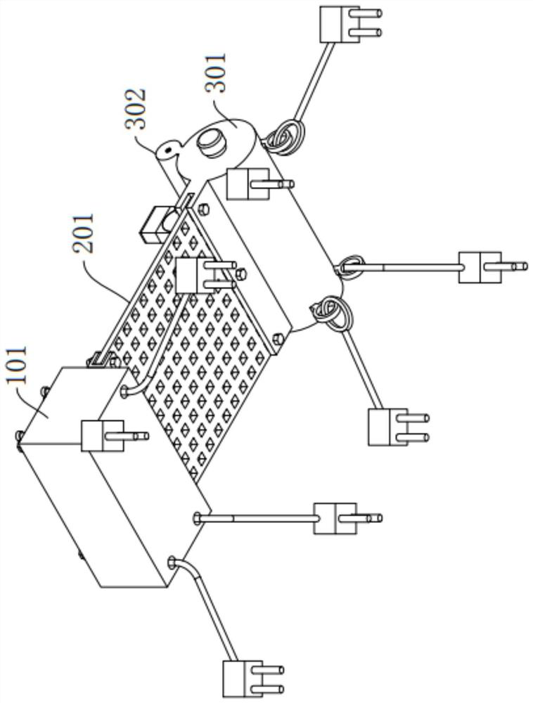
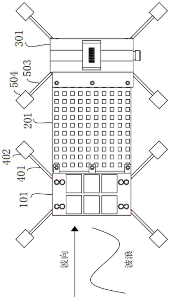
[0055] Such as figure 1 As shown, a combined floating wave extinguishing and anti-wave equipment according to an embodiment of the present invention includes a combined floating wave extinguishing and anti-wave equipment, including a first wave extinction mechanism 1, a second wave extinction mechanism 2, a first wave extinction mechanism Three wave dissipating mechanisms 3, the first mooring mechanism 4 and the second mooring mechanism 5,
[0056] Among them, such as figure 1 with Figure 10 As shown, the first wave dissipation mechanism 1 includes a buoyancy tank 101, the buoyancy tank 101 is a rectangular box structure, and the buoyancy tank 101 is made of reinforced concrete, and the inside of the buoyancy tank 101 is evenly provided with Several closed compartments 102;
[0057] Among them, such as Figure 1-Figure 7 As shown, the second wave dissipation mechanism 2 includes a net 201, the net 201 is woven into a thin layer structure by nylon rope, and there are sever...
Embodiment 2
[0067] Such as figure 1 with Figure 5 as well as Figure 8-Figure 9As shown, the difference between this embodiment and Embodiment 1 is that it also includes a remote alarm device 6, and the remote alarm device 6 includes a mounting base 601, a first box body 602, a side cover 605, a boom 610, a U-shaped A hinged seat 612, a connecting rod 614, a spherical block 613, two proximity sensors 609, a second box body 603, a solar panel 604, a storage battery 606, a controller 607 and a communication module 608, the mounting seat 601 is fixedly installed on the The upper part of the cylindrical hollow water bag 301, and the mounting seat 601 is arranged across the cylindrical hollow air bag 302, the first box body 602 is fixedly installed on the upper part of the mounting seat 601, and the side cover plate 605 Fixedly installed on one side of the first box body 602, the suspension rod 610 is vertically and fixedly installed on the bottom of the inner top wall of the first box body...
Embodiment 3
[0071] Such as Figure 4 with 10 with Figure 13 As shown, the difference between this embodiment and Embodiment 2 is that the insides of several of the airtight compartments 102 are filled with plastic foam blocks 103, and one end of the cylindrical hollow water bag 301 is integrally provided with a water injection port 303 , the water injection port 303 communicates with the interior of the cylindrical hollow water bag 301, and the exterior of the water injection port 303 is screwed with a sealing cover 304, and one end of the cylindrical hollow air bag 302 is embedded with a Internally communicated air valve 305, the outer diameter of the cylindrical hollow water bag 301 is greater than the outer diameter of the cylindrical hollow air bag 302, and the connection between the cylindrical hollow water bag 301 and the cylindrical hollow air bag 302 The body is 8-shaped, and the cylindrical hollow water bladder 301 and the cylindrical hollow air bladder 302 are both made of ru...
PUM
 Abstract
Description
Claims
Application Information
 - R&D
- Intellectual Property
- Life Sciences
- Materials
- Tech Scout
- Unparalleled Data Quality
- Higher Quality Content
- 60% Fewer Hallucinations
Browse by: Latest US Patents, China's latest patents, Technical Efficacy Thesaurus, Application Domain, Technology Topic, Popular Technical Reports.
© 2025 PatSnap. All rights reserved.Legal|Privacy policy|Modern Slavery Act Transparency Statement|Sitemap|About US| Contact US: help@patsnap.com


