Composite shot blasting device and method utilizing pellet kinetic energy and ultrasonic vibration

A technology of ultrasonic vibration and shot peening device, applied in the field of material processing, can solve the problems of limited surface material strengthening effect, reduced speed of pellets colliding with workpiece, affecting ultrasonic shot peening effect, etc., so as to improve strengthening efficiency and strengthening effect, and reduce damage. , the effect of severe plastic deformation

Active Publication Date: 2020-11-17
SOUTH CHINA UNIV OF TECH
View PDF6 Cites 6 Cited by
  • Summary
  • Abstract
  • Description
  • Claims
  • Application Information

AI Technical Summary

Problems solved by technology

During the working process, almost all the pellets collide and rub against each other, which reduces the speed at which the pellets collide with the workpiece and affects the strengthening effect; it also breaks many pellets, and the broken pellets cannot be separated in time during the working process. , will affect the effect of ultrasonic shot peening and reduce work efficiency
Moreover, relying on purely ultrasonically driven pellets to hit the workpiece, the strengthening effect on the surface material is limited.

Method used


Image

  • Composite shot blasting device and method utilizing pellet kinetic energy and ultrasonic vibration
  • Composite shot blasting device and method utilizing pellet kinetic energy and ultrasonic vibration

Examples


Embodiment 1

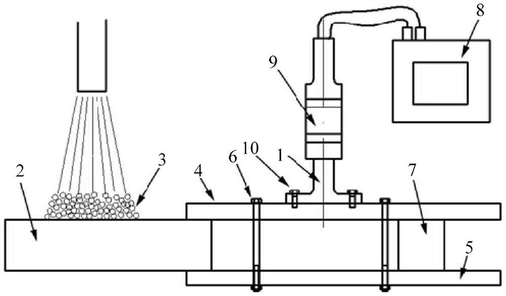
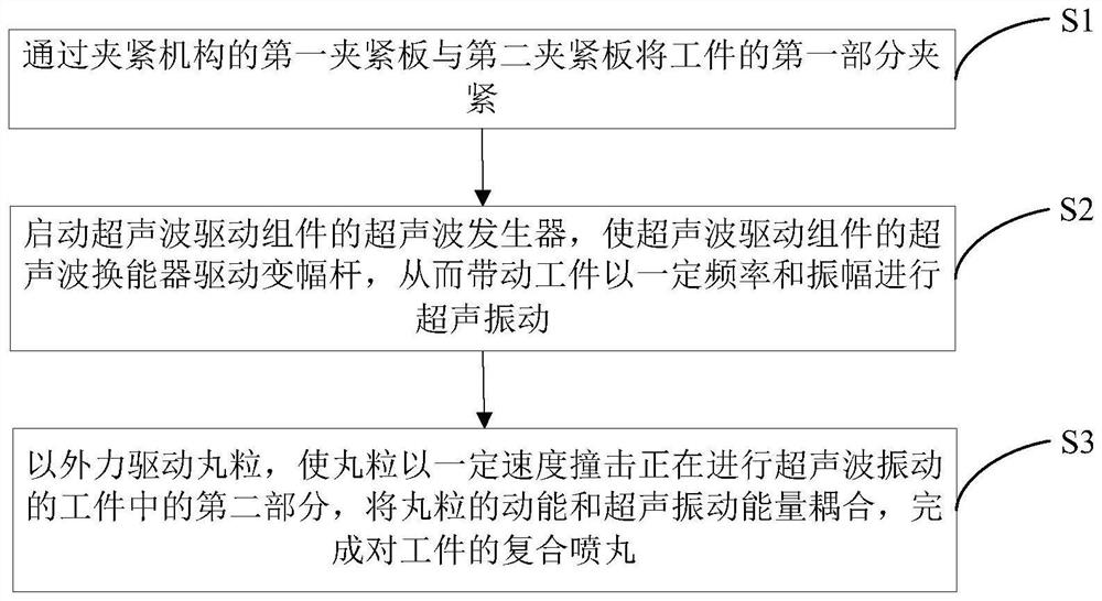
[0032] Such as figure 1 As shown, the present embodiment provides a compound shot peening device utilizing pellet kinetic energy and ultrasonic vibration, which device includes an ultrasonic drive assembly, a horn 1 and a clamping mechanism, and the clamping mechanism is used to clamp a part of the workpiece 2 Tight, the clamped part is the first part of the workpiece 2, the ultrasonic drive assembly is connected with the horn 1, the horn 1 is fixedly connected with the clamping mechanism, and the ultrasonic drive assembly is used to drive the horn 1 to drive the workpiece 2. Perform ultrasonic vibration; when the workpiece 2 is undergoing ultrasonic vibration, the external force drives the pellet 3 to hit the rest of the workpiece 2 except for the clamping mechanism, and the rest of the workpiece 2 is the second part of the workpiece 2 except for the clamping mechanism.

[0033] Further, the clamping mechanism includes a first clamping plate 4 and a second clamping plate 5, a...

Embodiment 2

[0043] The main feature of this embodiment is that the pellets 3 are driven by a mixture of compressed air and water. All the other are with embodiment 1.

Embodiment 3

[0045] The main feature of this embodiment is that the pellets 3 are driven by means of a drive mode in which the pellets 3 are thrown by relevant mechanical parts. All the other are with embodiment 1.


PUM

PropertyMeasurementUnit
diameteraaaaaaaaaa

Abstract

The invention discloses a composite shot blasting device and method utilizing pellet kinetic energy and ultrasonic vibration. The device comprises an ultrasonic driving assembly, an amplitude-change pole and a clamping mechanism, wherein the clamping mechanism is used for clamping one part of a workpiece, the ultrasonic driving assembly is connected with the amplitude-change pole, the amplitude-change pole is fixedly connected with the clamping mechanism, and the ultrasonic driving assembly is used for driving the amplitude-change pole so as to drive the workpiece to perform ultrasonic vibration; and when the workpiece is subjected to ultrasonic vibration, pellets are driven by an external force to impact other parts of the workpiece except for the part clamped by the clamping mechanism. According to the device, the pellets with certain kinetic energy can impact the workpiece in ultrasonic vibration, the kinetic energy of the pellets and ultrasonic vibration energy are compounded, thesurface of a material is strengthened, the shot blasting strengthening effect is improved, a special sealing bin for placing the workpiece and the pellets for common ultrasonic shot blasting is not needed, and broken pellets can be cleaned up and separated in time, so that the cost is reduced, the working efficiency is improved, and the strengthening effect is enhanced.

Description

technical field [0001] The invention relates to a compound shot peening device and method utilizing shot kinetic energy and ultrasonic vibration, belonging to the technical field of material processing. Background technique [0002] With the development of industries such as aerospace, marine engineering, automobile industry, chemical industry, construction machinery and transportation, equipment and parts work under more severe working conditions, the surface morphology and wear resistance of equipment and parts Performance, corrosion resistance and fatigue resistance put forward higher requirements. The surface properties and state of materials have a great influence on the wear, corrosion and fatigue performance of parts, because wear, corrosion and fatigue cracks generally first initiate on the surface of parts and expand from the surface, leading to failure of parts. Therefore, strengthening the material surface can prevent, delay or even eliminate the occurrence of we...

Claims


Application Information

Patent Timeline
Patent Type & Authority Applications(China)
IPC IPC(8): B24C1/00B24C3/02B24C9/00
CPCB24C1/00B24C3/02B24C9/00
Inventor 屈盛官任朝军贾思钰胡雄风李小强
Owner SOUTH CHINA UNIV OF TECH
Why Eureka
Try Eureka