Anti-atomization raw material transportation robot for chemical production

A chemical production and anti-fogging technology, applied in the field of robotics, can solve problems such as physical harm to workers

Pending Publication Date: 2020-11-17
陈保柱
View PDF5 Cites 0 Cited by
  • Summary
  • Abstract
  • Description
  • Claims
  • Application Information

AI Technical Summary

Problems solved by technology

[0004] The purpose of the present invention is to provide a chemical production anti-atomization raw material transportation robot that can automatically absorb acid mist in view of the above-mentioned problem that the atomization of acid liquid causes harm to the health of workers

Method used


Image

  • Anti-atomization raw material transportation robot for chemical production
  • Anti-atomization raw material transportation robot for chemical production

Examples


Embodiment 1

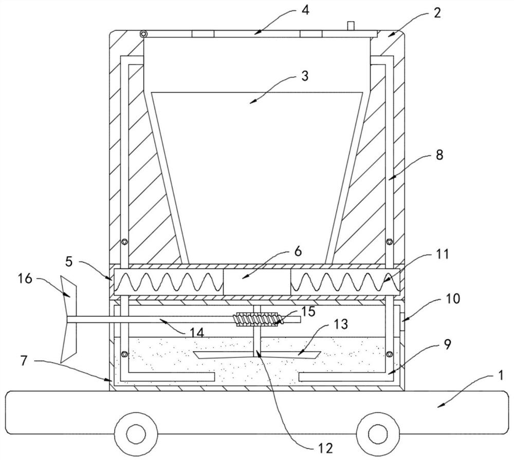
[0018] like figure 1 As shown, an anti-atomization raw material transportation robot for chemical production includes a base 1 and a heat preservation cylinder 2. The heat preservation cylinder 2 is provided with a groove in the shape of a round table, and a liquid holding bucket 3 is arranged in the groove. The upper end of 2 is hinged with an upper cover 4, and a through hole is provided in the upper cover 4. A negative pressure tube 5 arranged horizontally is installed on the bottom of the heat preservation tube 2, and a slider 6 is sealed and slidably connected in the negative pressure tube 5, and the slider 6 passes through The spring 11 is fixedly connected to the inner side wall of the negative pressure pipe 5, the lower end of the negative pressure pipe 5 is fixedly installed with a defogging box 7, and both ends of the negative pressure pipe 5 are fixedly connected with a one-way suction pipe 8 and a one-way exhaust pipe 9. The upper end of the one-way suction pipe 8 ...

Embodiment 2

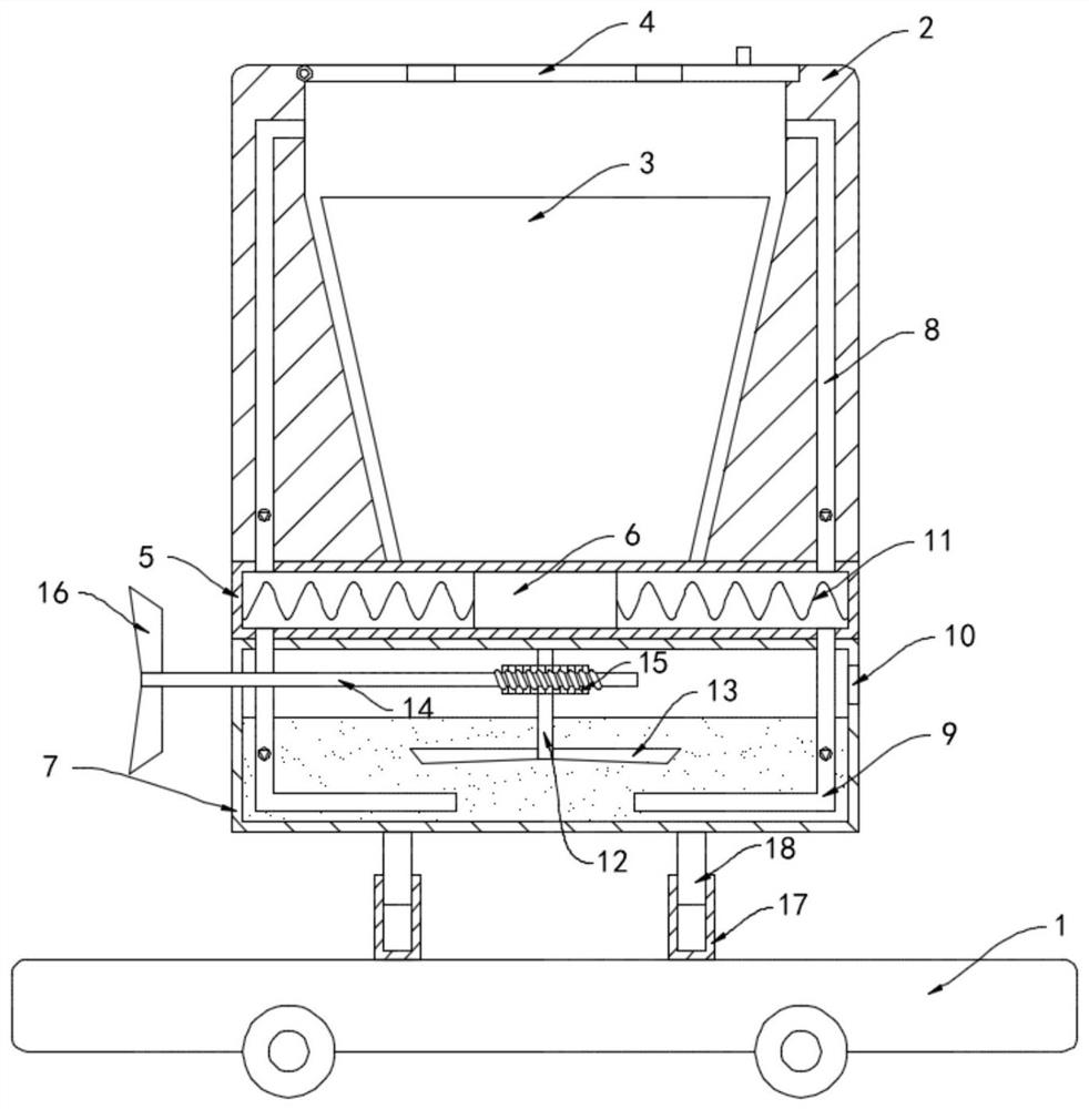
[0023] like figure 2 As shown, the difference between this embodiment and Embodiment 1 is that: the upper surface of the base 1 is fixedly connected with a sleeve 17, and a lifting rod 18 is sealed and slid inside the sleeve 17, and the upper end of the lifting rod 18 is fixed to the defogging box 7 To connect, the sleeve 17 is filled with thermal expansion and contraction medium, and the thermal expansion and contraction medium is one or more of kerosene, mercury and methylene chloride.

[0024] In this embodiment, when the transport robot is driving on a bumpy road section, shaking repeatedly causes a large amount of acid solution to volatilize and atomize, then the acid solution and the alkaline solution undergo neutralization reactions in the demister box 7, generating a large amount of heat. Conducted to the sleeve 17 through the lifting rod 18, the thermal expansion and contraction medium expands when the temperature rises, pushing the lifting rod 18 to move upward, and...


PUM


Abstract

The invention belongs to the field of robots, and particularly relates to an anti-atomization raw material transportation robot for chemical production, which comprises a base and a heat preservationcylinder, a groove in an inverted circular truncated cone shape is formed in the heat preservation cylinder, a liquid containing barrel is arranged in the groove, an upper cover is hinged to the upperend of the heat preservation cylinder, and a through hole is formed in the upper cover; a horizontally-arranged negative pressure pipe is installed at the bottom of the heat preservation cylinder, asliding block is connected into the negative pressure pipe in a sealed and sliding mode, a demisting box is fixedly installed at the lower end of the negative pressure pipe, the two ends of the negative pressure pipe fixedly communicate with a one-way air suction pipe and a one-way air exhaust pipe correspondingly, and the upper end of the one-way air suction pipe extends into the heat preservation cylinder. The lower end of the one-way exhaust pipe extends to the inner bottom face of the demisting box, and an alkaline solution is contained in the demisting box. Volatilized and atomized acid mist can be sucked into the demisting box to be absorbed under the action of inertia force, and it is avoided that when a worker opens the upper cover, the scattered acid mist harms the body of the worker.

Description

technical field [0001] The invention belongs to the field of robots, in particular to an anti-atomization raw material transportation robot for chemical production. Background technique [0002] With the development of robot technology, more and more robots are used in the field of chemical production instead of manual labor, which greatly improves production efficiency and reduces the probability of accidents and losses. Among them, chemical raw material transportation robots are used in actual During use, due to bumpy roads and other reasons, some concentrated acid chemical raw materials are easy to volatilize and atomize, and accumulate in the transport robot. After transporting to the designated place, the staff opens the cover, and the volatilized acid mist floats out. cause great harm to the human body. [0003] To this end, we propose an anti-atomization raw material transportation robot for chemical production to solve the above problems. Contents of the invention...

Claims


Application Information

Patent Timeline
Patent Type & Authority Applications(China)
IPC IPC(8): B60P3/00B08B15/02
CPCB60P3/00B08B15/02
Inventor 陈保柱
Owner 陈保柱
Why Eureka
Try Eureka