Articulated engineering machinery, panoramic look-around system and calibration method thereof

A technology for construction machinery and panoramic surround view, which is applied in control devices, transportation and packaging, and vehicle parts, etc. It can solve the problems of limited high field of vision in the cab, increased operational difficulty, and blind spots in the driver's field of vision, and achieves the effect of easy image splicing

Pending Publication Date: 2020-11-17
XCMG CONSTR MACHINERY
View PDF7 Cites 2 Cited by
  • Summary
  • Abstract
  • Description
  • Claims
  • Application Information

AI Technical Summary

Problems solved by technology

Usually construction machinery can only rely on rearview mirrors or reversing images to assist in observing the surrounding environment during the construction process. However, due to the presence of obstacles such as the front of the car, windows, and pillars, and the generally high view of the construction machinery cab, the driver There is a blind area in the field of vision, and it is impossible to judge whether there are obstacles in the occlusion area and the distance between obstacles
[0003] Moreover, in order to improve the flexibility of steering and operation of construction machinery, there have been construction machinery in which the cab and the rear frame are connected through a hinge mechanism. During the steering process of construction machinery, the angle of the rear frame relative to the cab is constantly changing. Therefore, it is more difficult for the driver to judge the environment around the construction machinery, which increases the difficulty of operation and makes it difficult to ensure the safety of the driving process.

Method used


Image

  • Articulated engineering machinery, panoramic look-around system and calibration method thereof
  • Articulated engineering machinery, panoramic look-around system and calibration method thereof
  • Articulated engineering machinery, panoramic look-around system and calibration method thereof

Examples


no. 1 example

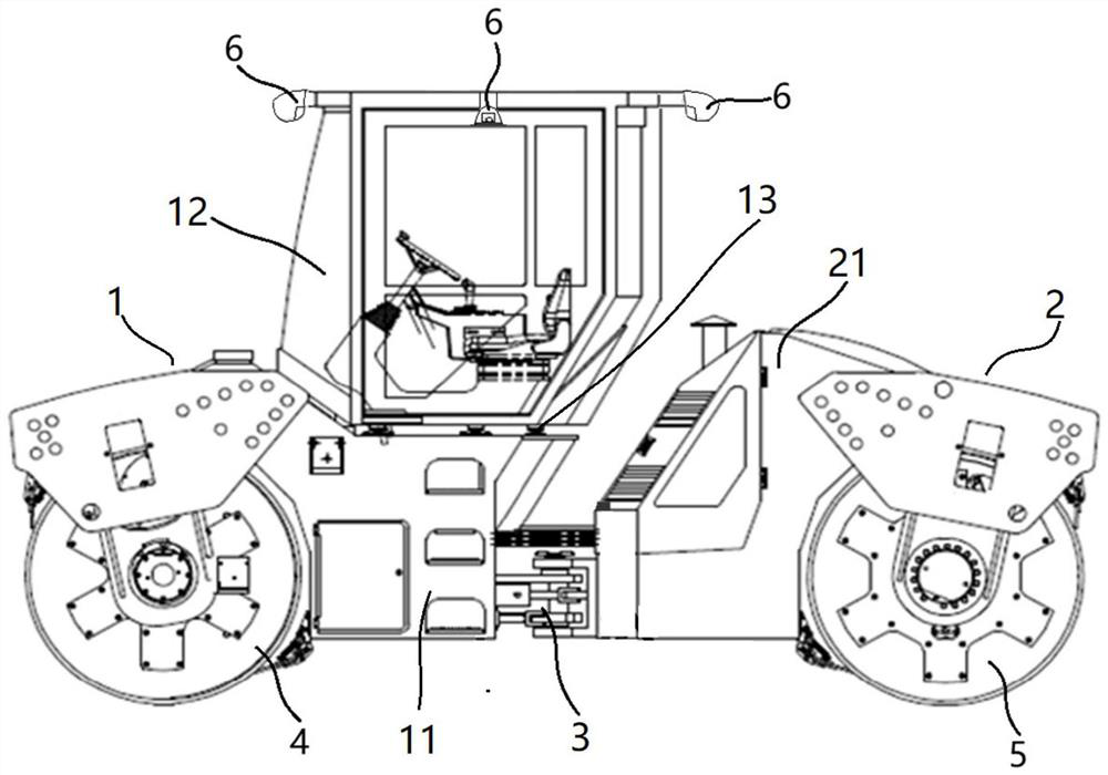
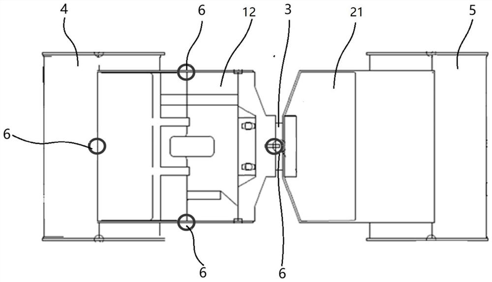
[0116] For the first embodiment, such as Figure 3A to Figure 3D As shown, the four shooting components 6 are all arranged on the cab 12, and four calibration devices 7 are arranged on the reference plane outside the preset reference frame K. The specific method is as follows:

[0117] 1. If Figure 3A , to obtain the overall top view model of the articulated construction machinery;

[0118] 2. If Figure 3B , only keep the partial model of the area where the outline of the cab 12 is kept in the overall top view model, and the outline of the cab 12 refers to the actual outer edge of the cab 12;

[0119] 3. If Figure 3C , find the actual area corresponding to the part of the model in the actual vehicle body, and offset the preset distance L outward relative to the actual area, mark the preset reference frame K on the reference plane, and the preset reference frame K is a rectangle;

[0120] 4. If Figure 3D , the length of the first articulated structure section 1 is less...

no. 2 example

[0134] For the second embodiment, the arrangement of multiple calibration devices 7 differs from that of the first embodiment in that six calibration devices 7 are arranged on a reference plane outside the preset reference frame K, and the specific method is as follows:

[0135] 1. If Figure 6A , to obtain the overall top view model of the articulated construction machinery;

[0136] 2. If Figure 6B , the overall top view model retains only a partial model of the area where the first hinged structure section 1 outline is located, and the first hinged structure section 1 outline refers to the actual outer edge of the first hinged structure section 1;

[0137] 3. If Figure 6C , find the actual area corresponding to the part of the model in the actual vehicle body, and offset the preset distance L outward relative to the actual area, mark the preset reference frame K on the reference plane, and the preset reference frame K is a rectangle;

[0138] 4. If Figure 6D , when t...


PUM


Abstract

The invention relates to an articulated engineering machine, a panoramic look-around system and a calibration method thereof. The articulated engineering machine comprises at least two articulated structure sections which are sequentially connected through an articulated frame (3), the at least two articulated structure sections comprise the first articulated structure section (1), and the first articulated structure section comprises a first vehicle body (11) and a cab (12) arranged on the first vehicle body (11); the panoramic look-around system comprises a plurality of shooting parts (6) which are installed on a first hinge structure section (1) and configured to shoot the environment around the hinge type engineering machine; an image processing component (8) which is configured to receive the images shot by the plurality of shooting components (6) and splice the images into a look-around image of the whole circumference of the first hinge structure section (1); and a man-machine interaction component (9) which is configured to display the panoramic image formed by splicing the image processing components (8).

Description

technical field [0001] The present disclosure relates to the technical field of construction machinery driving assistance, and in particular to an articulated construction machinery, a panoramic view system and a calibration method thereof. Background technique [0002] The development of modern science and technology has greatly promoted the intelligence of construction machinery, and more and more high-end technologies have been introduced into the field of construction machinery, making construction machinery move towards more efficient and safer goals. Usually construction machinery can only rely on rearview mirrors or reversing images to assist in observing the surrounding environment during the construction process. However, due to the existence of obstacles such as the front of the car, windows, and pillars, and the generally high view of the construction machinery cab, the driver There are blind spots in the field of vision, and it is impossible to judge whether ther...

Claims


Application Information

Patent Timeline
Patent Type & Authority Applications(China)
IPC IPC(8): B60W30/18B60W40/02B60W50/14B60R11/04
CPCB60W30/18B60W40/02B60W50/14B60R11/04B60W2050/146E01C19/42B60R2300/303B60R2300/20B60R2300/105B60R2300/802B60R2300/102B60R1/27B60R2300/402
Inventor 崔吉胜武博文庄坤张天骄薛力戈
Owner XCMG CONSTR MACHINERY
Why Eureka
Try Eureka