Green building rainwater collection device
A rainwater collection device and green building technology, applied in water supply devices, drinking water devices, buildings, etc., can solve problems such as inability to use household collection, inability to use high-rise buildings, water loss and waste, etc., to eliminate potential safety hazards and save occupation. space, to achieve the effect of automatic control
- Summary
- Abstract
- Description
- Claims
- Application Information
AI Technical Summary
Problems solved by technology
Method used
Image
Examples
Embodiment 1
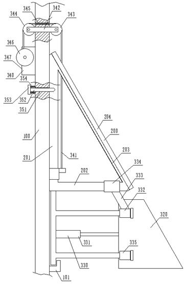
[0028] see figure 1 , the present invention provides a green building rainwater collection device, including a solar device 200 installed on the wall 100 and a rainwater collection mechanism that can be shrunk under the solar device 200;
[0029] The solar device 200 comprises a vertical mounting plate 201, a horizontal mounting plate 202, and an oblique mounting plate 203 fixed end to end to form a tripod, and a solar panel 204 arranged on the upper surface of the oblique mounting plate 203, and the vertical mounting plate 201 fixedly installed on the wall 100;
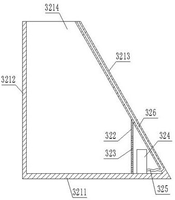
[0030] The rainwater collection mechanism includes a lifting frame 310 that can move along the vertical mounting plate 201, a vertical lifting mechanism 340 that pulls the lifting frame 310 up and down, a triangular water tank 320 that can slide horizontally on the lifting frame 310, and a triangular water tank 320 that is pulled horizontally Move the horizontal movement mechanism 330 .
Embodiment 2
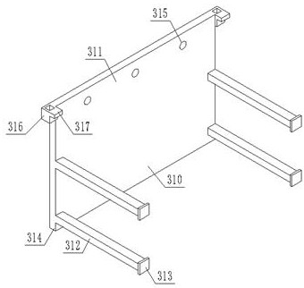
[0032] see figure 2 , on the basis of Embodiment 1, the lifting frame 310 includes a vertical base plate 311, two guide rods 312 are respectively arranged on the left and right sides of the vertical base plate 311, and the guide rods 312 are divided into an upper guide rod and a lower guide rod, and the vertical base plate The bottom of 311 is provided with a vertically downward inserting plate 314, the upper part of the vertical base plate 311 is provided with three positioning holes 315, the two sides of the vertical base plate 311 are provided with guide sleeves 316, and the guide sleeves 316 are provided with horizontal traction plates 317, The guide sleeve 316 is movably socketed on the vertical mounting plate 201;
[0033] The wall 100 is provided with a slot 101 used in conjunction with the plugboard 314;
[0034] The vertical lifting mechanism 340 includes a traction rope 341, a fixed plate 342 inserted in the body of wall 100, an outer pulley 343 and an inner pulley...
Embodiment 3
[0036] see figure 1, on the basis of Embodiment 1, a lower through hole 351 is provided on the wall 100, and an insertion rod 352 is slidably fitted in the lower through hole 351. The end of the insertion rod 352 away from the solar device 200 is provided with a connecting plate 353, and the connecting plate 353 A spring 354 is provided between the wall 100, and the insertion rod 352 can pass through the lower through hole 351 and be inserted into the positioning hole 315 under the drive of the spring 354, so as to limit the vertical movement of the lifting frame;
[0037] The horizontal moving mechanism 330 includes an electric cylinder 331 arranged on the lifting frame 310. The telescopic rod of the electric cylinder 331 is connected to the triangular water tank 320, and an upper sliding sleeve 334 is slidably fitted on the horizontal mounting plate 202, and is slidably fitted on the upper guide rod. There is a middle sliding sleeve 332, an upper sliding sleeve 334 is rotati...
PUM
 Abstract
Description
Claims
Application Information
 - R&D
- Intellectual Property
- Life Sciences
- Materials
- Tech Scout
- Unparalleled Data Quality
- Higher Quality Content
- 60% Fewer Hallucinations
Browse by: Latest US Patents, China's latest patents, Technical Efficacy Thesaurus, Application Domain, Technology Topic, Popular Technical Reports.
© 2025 PatSnap. All rights reserved.Legal|Privacy policy|Modern Slavery Act Transparency Statement|Sitemap|About US| Contact US: help@patsnap.com


