Stamping assembly type guardrail and assembling equipment thereof

An assembly equipment and assembly technology, applied in the direction of fences, building types, non-rotational vibration suppression, etc., can solve the problems of welding guardrail processing troubles, high maintenance costs, low labor efficiency, etc., to avoid Faraday shielding effect, installation Convenient and fast, stable and reliable installation

Pending Publication Date: 2020-11-17
杨义远
View PDF4 Cites 2 Cited by
  • Summary
  • Abstract
  • Description
  • Claims
  • Application Information

AI Technical Summary

Problems solved by technology

Assembling welding guardrails is not only troublesome and costly to process, but also the smoke and dust during assembly welding will cause environmental pollution and cause harm to the health of relevant personnel
In addition, the welding process causes defects such as deformation and corrosion of the pipe fittings, and the surface paint coating is seriously peeled off, resulting in high repair and maintenance costs in the later stage, and the need for repainting and other processes in the later stage
[0003] Most of the existing guardrails are assembled manually, that is, after a plurality of holes are opened on the beam, at least two beams are placed in parallel so that the holes on the two beams are aligned, and then each longitudinal beam is manually inserted into the In the corresponding hole, this method is labor-intensive and its labor efficiency is low. After insertion, use a welding machine to weld the insertion part
Finally, the spraying process is carried out, because there are easy gaps in the welding parts, so in the electrostatic spraying, the Faraday shielding effect will inevitably appear, and there will be no protective paint attached to some areas, so the anti-corrosion performance of the entire guardrail is poor

Method used


Image

  • Stamping assembly type guardrail and assembling equipment thereof
  • Stamping assembly type guardrail and assembling equipment thereof
  • Stamping assembly type guardrail and assembling equipment thereof

Examples


Embodiment Construction

[0025] The specific embodiment of the present invention is described in further detail below in conjunction with accompanying drawing:

[0026] refer to Figure 4 As shown, in the prior art, the crossbeam is pre-drilled, and a plurality of insertion holes are opened on the crossbeam. After the crossbeam is placed on a platform, a single longitudinal beam is manually inserted into the insertion hole for assembly. After assembly, welding is carried out at the X position in the figure, so that the beam and the longitudinal beam are firmly connected to form a guardrail. Since the difference between the peripheral size of the longitudinal beam and the size of the insertion hole is very small (up to about 0.5mm), the insertion is very easy. Inconvenient, low labor efficiency and high labor intensity, and the welding is prone to Faraday effect, rust and reduce the service life of the product.

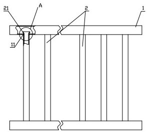
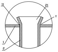
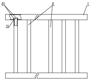
[0027] as attached figure 1 and figure 2 As shown, the embodiment of the stamped assem...


PUM


Abstract

The invention discloses a stamping assembly type guardrail and an assembling equipment thereof. The stamping assembly type guardrail comprises two transverse beams which are arranged at intervals andtransversely arranged and longitudinal beams which are arranged at intervals and vertically arranged, a plurality of inserting holes which are distributed at intervals are formed in each of the transverse beams, the inserting holes of the upper transverse beam and the lower transverse beam that are adjacent are vertically aligned, the inserting holes in the transverse beams are blind holes formedtowards the inner side, the multiple longitudinal beams are inserted into the aligned inserting holes through the assembling equipment to achieve inserting connection between the multiple longitudinalbeams and the transverse beams, the two sides of the hole walls of the inserting holes extend outwards to form pressing and leaning parts, after the end parts of the longitudinal beams extend into the inserting holes, the end parts of the longitudinal beams are bent outwards to form pressing and extending edges through a stamping device of the assembling equipment, and the pressing and extendingedges are pressed against the pressing and leaning parts to realize firm connection between the transverse beams and the longitudinal beams. According to the stamping assembly type guardrail and the assembling equipment thereof, welding can be avoided, assembling is directly carried out by means of the assembling equipment, so that installation is stable, the Faraday shielding effect in electrostatic spraying can be avoided, and the guardrail has better anti-corrosion performance.

Description

technical field [0001] The invention relates to a stamping assembled guardrail and its assembly equipment. Background technique [0002] At present, the known guardrails are assembled and welded by materials such as iron, aluminum, and stainless steel. Assembling welding guardrails is not only troublesome and costly to process, but also the smoke and dust during assembly welding will cause environmental pollution and cause harm to the health of relevant personnel. In addition, the welding process causes defects such as deformation and corrosion of the pipe fittings, and the paint coating on the surface is seriously peeled off, resulting in high maintenance costs in the later period, and the need for repainting and other processes in the later period. [0003] Most of the existing guardrails are assembled manually, that is, after a plurality of holes are opened on the beam, at least two beams are placed in parallel so that the holes on the two beams are aligned, and then eac...

Claims


Application Information

Patent Timeline
Patent Type & Authority Applications(China)
IPC IPC(8): E04H17/14B21D39/00F16F15/04
CPCE04H17/1413B21D39/00F16F15/04
Inventor 杨森杨义远
Owner 杨义远
Why Eureka
Try Eureka