
Method for searching equipment wear by using fluorescent indicator as indicator

A fluorescent indicator, indicator technology, applied in the direction of fluorescence/phosphorescence, material analysis by optical means, measurement device, etc., can solve slow wear, one is uncontrollable, such as entering foreign objects or between transmission mechanisms Abnormal collision, inability to eliminate the impact of wear debris product quality, inability to quickly locate minor wear and other problems, to achieve high promotion and application value, eliminate quality impact, eliminate product static electricity effect

Inactive Publication Date: 2020-11-17
广东喜珍电路科技有限公司
View PDF7 Cites 1 Cited by
  • Summary
  • Abstract
  • Description
  • Claims
  • Application Information

AI Technical Summary

Problems solved by technology

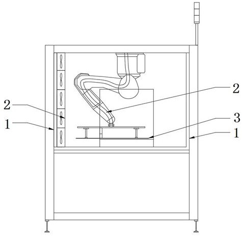
During the use of equipment, various wear and tear will occur over time. One kind of wear is predictable, such as bearings and transmission parts, which will slowly wear out after a certain period of time, and the other is uncontrollable. Such as foreign matter entering or abnormal collision between transmission mechanisms, such as the retractable trigger in the circuit board industry, the main body is an inverted manipulator, which is connected to the suction cup to absorb the PCB and place it. During the operation, the external vacuum tube has various reasons. The possibility of friction with the arm is usually fixed by fixing the vacuum tube or adding a cloth cover. In fact, as the running time increases, abrasive debris will contaminate the board surface and cause quality problems. The difficulty here is that when slight wear occurs, it cannot be repaired in time. It is impossible to quickly locate the location of slight wear if there is any wear debris, and it is impossible to eliminate the impact of the generated wear debris on product quality

Method used


Image

  • Method for searching equipment wear by using fluorescent indicator as indicator

Examples


Embodiment 1

[0027] A method for finding equipment wear using a fluorescent indicator as an indicator, characterized in that it comprises the following specific steps:

[0028] S1. Prepare the fluorescent indicator and put it into the spraying tool;

[0029] S2. The equipment stops running and power off;

[0030] S3. Evenly spray a layer of fluorescent indicator on the area that may be worn out in the equipment, and after it dries out, use an ultraviolet light to check whether there is any leakage, and take pictures or videos for subsequent comparison;

[0031] S4. Install brand-new filter cotton 1 in the corresponding area where the fluorescent indicator is sprayed. During equipment maintenance or inspection, first check whether there is a fluorescent reaction on the filter cotton. If there is a fluorescent reaction, check the corresponding position of the equipment through the position of the fluorescent reaction. of wear and tear.

[0032] The present invention can realize visual equi...

Embodiment 2

[0045]This embodiment provides a method of using a fluorescent indicator as an indicator to find equipment wear that is the same as in Example 1. The difference is that the fluorescent indicator includes the following components in parts by weight: SrO 40-55, B2O3 21, P2O5 4, Gd2O3 1.5, MgO 27, La2O3 1.7, water-based polyurethane adhesive 85.

[0046] Further, the preparation method of the fluorescent indicator is as follows: Weigh the raw materials according to the ratio of parts by weight, grind and stir SrO, B2O3, P2O5, Gd2O3, MgO, La2O3 evenly, and place them in a silicon carbide rod electric furnace at 750°C at high temperature Burn for 2.2 hours, after cooling, take out the pulverized ball and pass through a 350-mesh sieve to obtain ultraviolet fluorescent powder. Mix the ultraviolet fluorescent powder into water-based polyurethane adhesive and disperse evenly at high speed to obtain a fluorescent indicator.

[0047] In the present invention, the phosphor powder with str...

Embodiment 3

[0049] This embodiment provides a method of using a fluorescent indicator as an indicator to find equipment wear that is the same as in Example 1. The difference is that the fluorescent indicator includes the following components in parts by weight: SrO 52, B2O3 35, P2O5 7 , Gd2O34, MgO 31, La2O3 2.2, water-based polyurethane adhesive 105.

[0050] Further, the preparation method of the fluorescent indicator is as follows: weigh the raw materials according to the ratio of parts by weight, grind and stir SrO, B2O3, P2O5, Gd2O3, MgO, and La2O3 evenly, and place them in a silicon carbide rod electric furnace at 1000°C at high temperature Burn for 2.8 hours, after cooling, take out the pulverized ball and pass through a 350-mesh sieve to obtain ultraviolet fluorescent powder. Mix the ultraviolet fluorescent powder into water-based polyurethane adhesive and disperse evenly at high speed to obtain a fluorescent indicator.

[0051] In the present invention, the phosphor powder with s...


PUM


Abstract

The invention provides a method for searching equipment wear by using a fluorescent indicator as an indicator, which comprises the following specific steps: S1, preparing the fluorescent indicator, and putting the fluorescent indicator into a spraying tool; s2, enabling the equipment to stop running and be powered off; s3, uniformly spraying a layer of fluorescent indicator on an area which is likely to be abraded in the equipment, checking whether the spraying is missed or not by using an ultraviolet lamp after the area is completely dried, and shooting a picture or a video for subsequent comparison; and S4, loading brand-new filter cotton into the corresponding area sprayed with the fluorescent indicator, checking whether the filter cotton has a fluorescent reaction or not during equipment maintenance or inspection, and if the fluorescent reaction occurs, checking the worn part of the corresponding position of the equipment through the position of the fluorescent reaction. The methodis simple to operate and low in cost, the abrasion condition can be quickly known by spraying the fluorescent indicator at the equipment and matching the filter cotton at the lower part, the existingequipment does not need to be greatly modified, and the popularization and application values are very high.

Description

technical field [0001] The invention belongs to the field of equipment manufacture and maintenance, and in particular relates to a method for finding equipment wear by using a fluorescent indicator as an indicator. Background technique [0002] Equipment is an important material condition for the production of enterprises. In order to carry out production, enterprises must spend a certain amount of investment to purchase various equipment. During the use of equipment, various wear and tear will occur over time. One kind of wear is predictable, such as bearings and transmission parts, which will slowly wear out after a certain period of time, and the other is uncontrollable. Such as foreign matter entering or abnormal collision between transmission mechanisms, such as the retractable trigger in the circuit board industry, the main body is an inverted manipulator, which is connected to the suction cup to absorb the PCB and place it. During the operation, the external vacuum ...

Claims


Application Information

Patent Timeline
Patent Type & Authority Applications(China)
IPC IPC(8): G01N21/64
CPCG01N21/643G01N2021/6432G01N2021/6439G01N2021/6417
Inventor 程文君
Owner 广东喜珍电路科技有限公司
Learn More