
Internal cascade solid oxide fuel cell stack with high fuel utilization rate

A technology of solid oxide and fuel cell stacks, applied in the direction of fuel cells, fuel cell additives, fuel cell heat exchange, etc., can solve the problem of limiting the promotion and application of solid oxide fuel cell technology, increasing the parasitic consumption of auxiliary equipment such as fans Power, affecting the net power generation efficiency of the system and other issues, to achieve the effect of improving net power generation efficiency, improving fuel utilization, and improving temperature field uniformity

Active Publication Date: 2020-11-17
TSINGHUA UNIV
View PDF8 Cites 1 Cited by
  • Summary
  • Abstract
  • Description
  • Claims
  • Application Information

AI Technical Summary

Problems solved by technology

[0003] In order to improve the performance of solid oxide fuel cell stacks, the existing battery stacks usually improve the fuel utilization rate by reducing the intake flow of fuel gas or increasing the operating current of the stack. Attenuation acceleration and other issues greatly affect the life of the battery stack; on the other hand, the cooling of the existing battery stack mainly depends on the cathode air, and the temperature of the stack is adjusted by adjusting the cathode air flow, but the above method will increase the parasitic consumption of auxiliary equipment such as fans. Power, which affects the net power generation efficiency of the system, greatly limits the promotion and application of solid oxide fuel cell technology

Method used


Image

  • Internal cascade solid oxide fuel cell stack with high fuel utilization rate
  • Internal cascade solid oxide fuel cell stack with high fuel utilization rate
  • Internal cascade solid oxide fuel cell stack with high fuel utilization rate

Examples


Embodiment Construction

[0029] In order to make the object, technical solution and advantages of the present invention clearer, the present invention will be further described in detail below in combination with specific embodiments and with reference to the accompanying drawings. It should be understood that these descriptions are exemplary only, and are not intended to limit the scope of the present invention. Also, in the following description, descriptions of well-known structures and techniques are omitted to avoid unnecessarily obscuring the concept of the present invention.

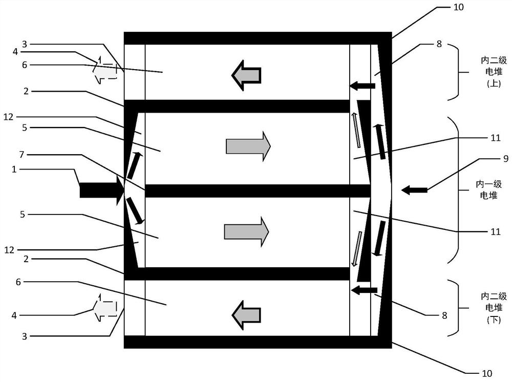
[0030] The high-efficiency heat management operation mode disclosed by the invention includes fuel gas composition management, internal reforming of the first-stage electric stack and double cooling of cathode air. Fuel gas composition management refers to the control of the fresh fuel gas composition provided by the main fuel supply pipeline to ensure that the reforming reaction of hydrocarbon fuel and the electrochemica...


PUM


Abstract

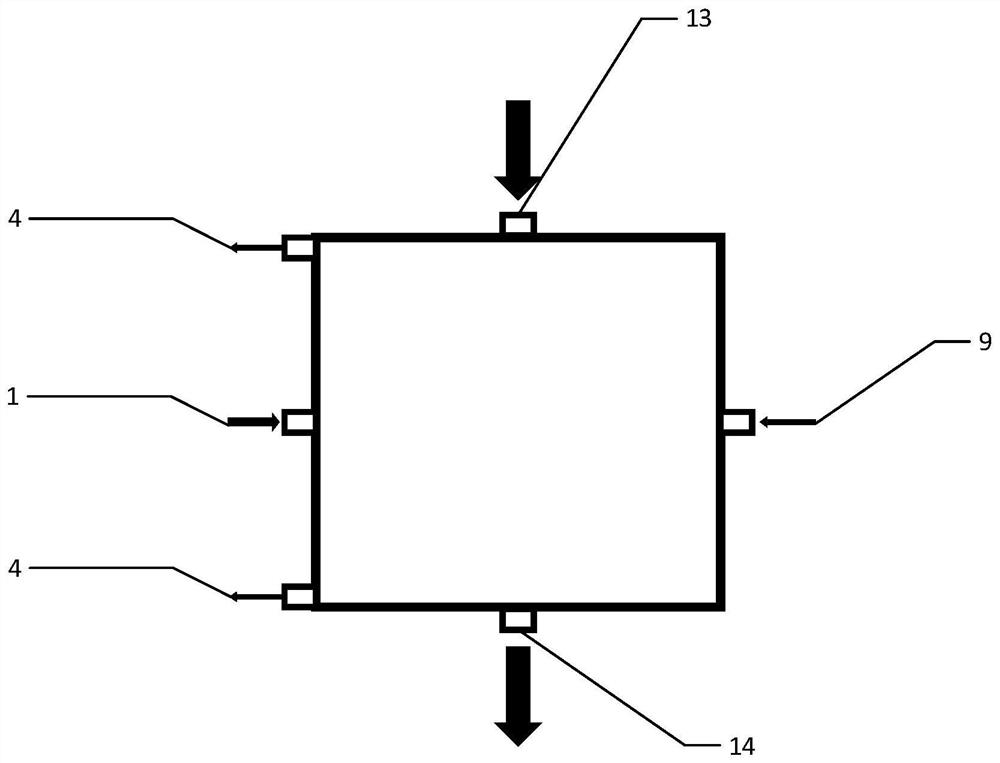
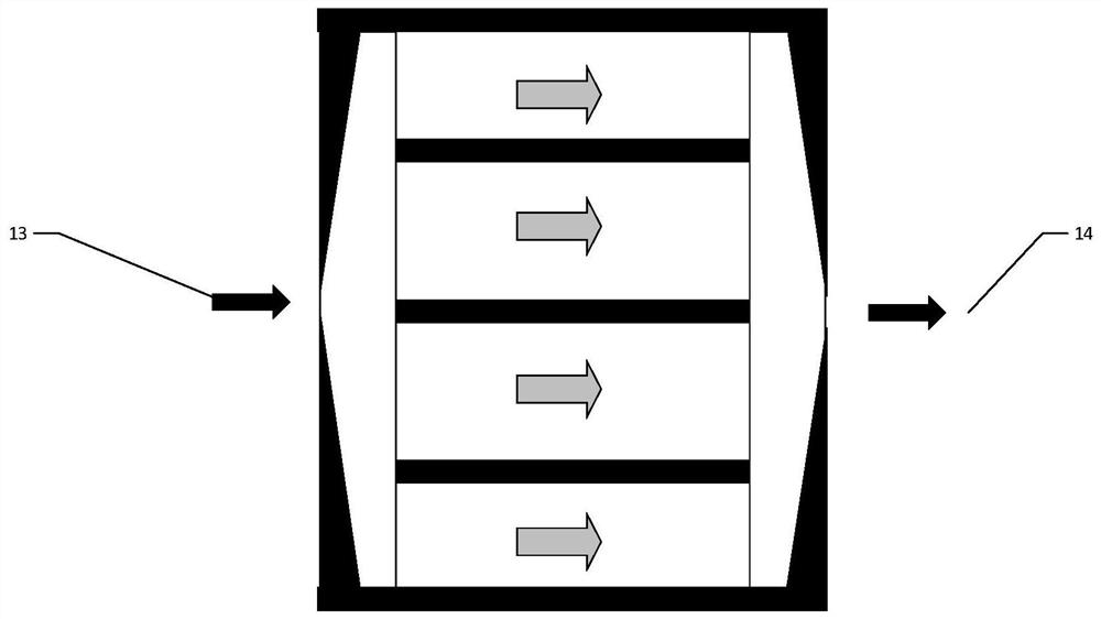
The invention relates to an internal cascade solid oxide fuel cell stack with a high fuel utilization rate. Fuel is input into an internal primary stack through a main fuel supply pipeline; air is input into the inner primary galvanic pile and the inner secondary galvanic pile through the air inlet; tail gas of the inner primary galvanic pile enters the inner secondary galvanic pile through a cascade circulation loop; fuel is supplemented to the inner secondary electric pile through an auxiliary fuel supply pipeline; and the inner secondary galvanic pile exhausts tail gas through a tail gas exhaust pipeline. The cascade loop is additionally arranged, so that the fuel utilization rate is increased; the inner primary galvanic pile in the middle position is additionally arranged, it is ensured that partial reforming reaction occurs in the inner primary galvanic pile by managing fuel gas components in the main fuel supply pipeline, the uniformity of the internal temperature field of the galvanic pile is improved, the internal temperature of the galvanic pile is reduced, and the parasitic power of a draught fan is reduced; and an auxiliary fuel supply pipeline is additionally arranged,so that the temperature of mixed fuel entering the internal secondary electric pile and the controllability of gas components are improved.

Description

technical field [0001] The invention relates to the technical field of solid oxide fuel cells, in particular to an internally cascaded solid oxide fuel cell stack with high fuel utilization. Background technique [0002] Solid Oxide Fuel Cell (SOFC) is a clean and efficient power generation device, which works at high temperature (600oC-1000oC), can directly use various hydrocarbon fuels such as methane, and convert the chemical energy in the fuel directly into electrical energy. The SOFC single cell and core components such as connectors and seals form a repeating unit, and multiple repeating units are stacked to form a solid oxide fuel cell stack. Due to the relatively simple preparation process of the planar solid oxide fuel cell and the high working current density, it has received widespread attention and key promotion at home and abroad. In recent years, the demand for high-power battery stacks has become increasingly urgent, and problems such as low primary fuel util...

Claims


Application Information

Patent Timeline
Patent Type & Authority Applications(China)
IPC IPC(8): H01M8/04014H01M8/04082H01M8/04089H01M8/04701H01M8/0612H01M8/0662H01M8/249
CPCH01M8/04014H01M8/04089H01M8/04097H01M8/04201H01M8/04701H01M8/0618H01M8/0662H01M8/249H01M2008/1293Y02E60/50
Inventor 朱建忠韩敏芳
Owner TSINGHUA UNIV
Learn More