A control method for a hierarchical series cooling system of low-temperature thermal fluid

A cooling system control, low-temperature heat technology, applied in steam engine installations, machines/engines, mechanical equipment, etc., can solve problems such as limiting the scope of application, and achieve the effect of expanding the scope of application, reducing initial investment, and improving net power generation efficiency

Active Publication Date: 2018-04-03
SICHUAN XINMA ENERGY TECH CO LTD
View PDF6 Cites 0 Cited by
  • Summary
  • Abstract
  • Description
  • Claims
  • Application Information

AI Technical Summary

Problems solved by technology

Sensitivity to the process cooling target temperature limits the application range of power generation cooling, which is a productive cooling method

Method used


Image

  • A control method for a hierarchical series cooling system of low-temperature thermal fluid
  • A control method for a hierarchical series cooling system of low-temperature thermal fluid
  • A control method for a hierarchical series cooling system of low-temperature thermal fluid

Examples


Embodiment 1

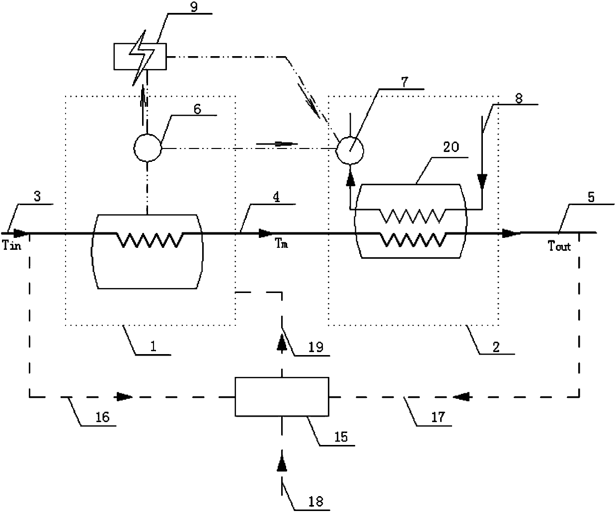
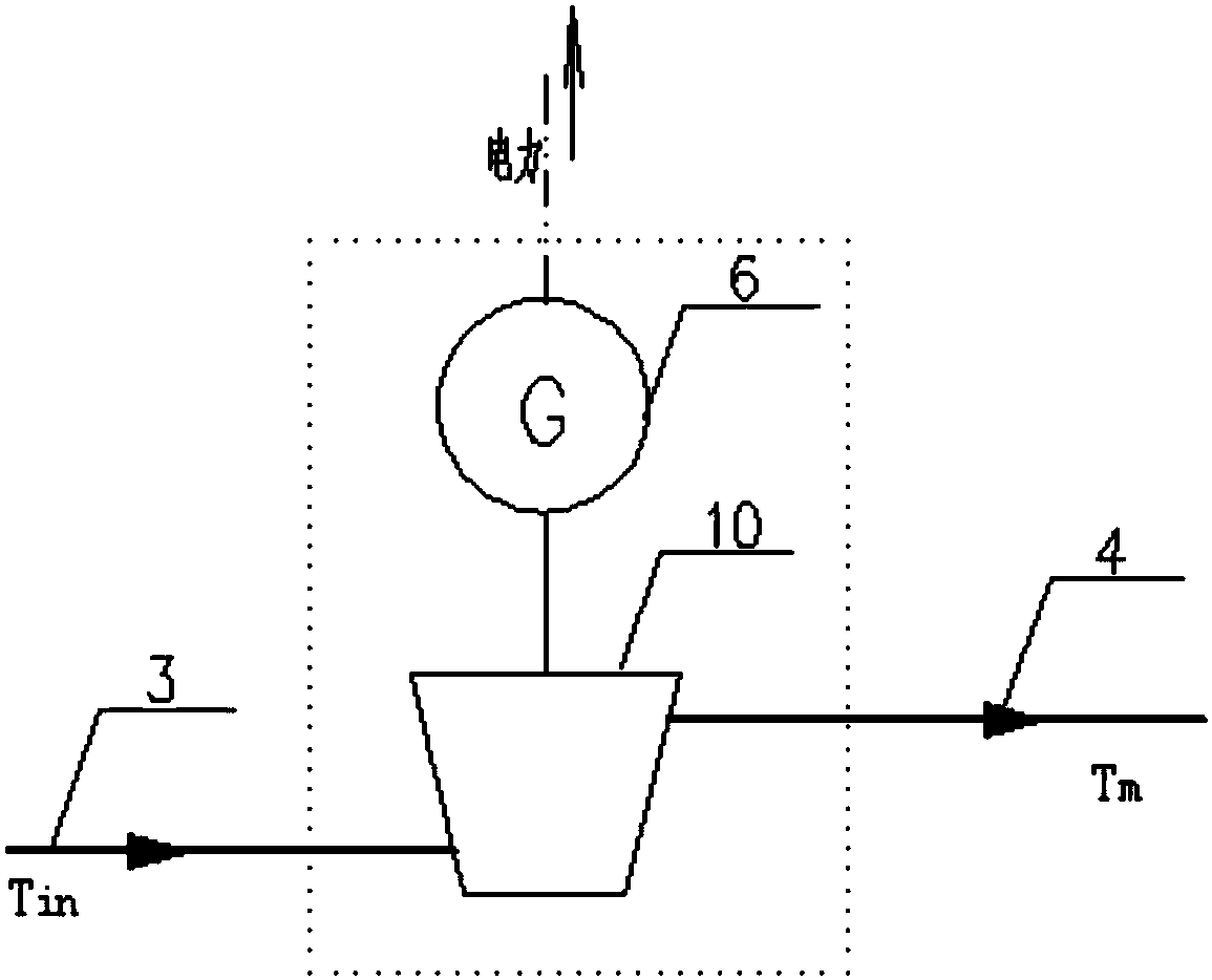
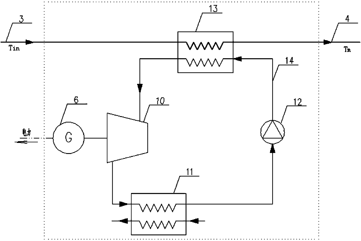
[0026] Such as Figure 1 to Figure 5 As shown, a hierarchical series cooling system of low-temperature thermal fluid, the system includes two-stage cooling units arranged in series, wherein the first-stage cooling unit is a power generation cooling unit 1, and the second-stage cooling unit is a conventional cooling unit 2; the inlet temperature is T in The thermal fluid 3 first enters the power generation cooling unit 1 and is cooled to a suitable intermediate temperature T m ; Power generation cooling unit 1 is cooled to an intermediate temperature of T m The thermal fluid 4 then enters the conventional cooling unit 2 and is finally cooled to the target outlet temperature T out , that is, the target outlet temperature is T out thermal fluid 5.

[0027] Preferably, the conventional cooling unit 2 includes a power device 7 (pump, fan, etc.) and a conventional cooling device 20: an air cooling device, a water cooling device, an evaporative cooling device, and a composite coo...

Embodiment 2

[0034] On the basis of the first embodiment, the present invention also includes a control unit 15, which is respectively connected to the power generation cooling unit 1 and the conventional cooling unit 2, and the control unit 15 is used to control the cooling capacity of each cooling unit.

[0035] Preferably, the intermediate temperature T m According to the optimal control target, combined with the process conditions and local meteorological conditions, the control unit 15 adopts the optimization algorithm to carry out reasonable setting and real-time adjustment, so as to realize the dynamic distribution of the cooling capacity undertaken by the two-stage cooling system, so that the hierarchical series cooling system as a whole is real-time in optimal operating condition.

[0036] Preferably, the control process of the control unit 15 of the hierarchical series cooling system is as follows: Step (1): The control unit 15 monitors and collects the inlet temperature T of the...

example

[0037] Example: For a coal-to-oil transformation process, the process heat fluid to be cooled is hot water, the flow rate is 6000t / h, the initial temperature of the hot water is 90°C, the target temperature required to be cooled is 40°C, and the local annual average ambient temperature is 15 ℃.

[0038] The energy consumption or production energy of the air cooling mode, the evaporative cooling mode, the power generation cooling mode and the hierarchical series cooling system of a low-temperature thermal fluid of the present invention are respectively calculated to further illustrate the effect of the present invention.

[0039] (1) Cooling load

[0040] The cooling load of the thermal fluid in this coal-to-oil conversion process can be calculated according to formula (1), and the calculation result of this example is 350000kW.

[0041] Q=c·m·Δt (1)

[0042] Among them, Q is the cooling load of the process thermal fluid (kW), c is the specific heat capacity of the process th...


PUM


Abstract

The invention discloses a staged series cooling system of a low temperature thermal fluid. The staged series cooling system comprises two stages of cooling units which are arranged in series, wherein the first stage of cooling unit is an electric generation cooling unit; the second stage of cooling unit is a conventional cooling unit; a thermal fluid with the inlet temperature Tin firstly enters the electric generation cooling unit and is then cooled to an appropriate intermediate temperature Tm; the thermal fluid cooled in the electric generation cooling unit to the intermediate temperature Tm enters the conventional cooling unit and is finally cooled to a target outlet temperature Tout. The staged series cooling system of the low temperature thermal fluid has the advantages as follows: (1) the thermal fluid outlet temperature of the electric generation cooling unit is improved, the net electric generation efficiency of the electric generation cooling unit is improved, the initial cost of the electric generation cooling unit is reduced, and the electric generation cooling technology and economy are effectively improved; (2) the net electric generation of the electric generation cooling unit is usually greater than the power consumption of the conventional cooling unit, the electric energy is not consumed in the process of cooling the thermal fluid, electric generation benefits are achieved, and a good energy conservation and environmental protection effect is realized.

Description

technical field [0001] The invention relates to the technical field of low-temperature thermal fluid cooling, in particular to a control method for a hierarchical series cooling system of low-temperature thermal fluid. Background technique [0002] In coal chemical, petrochemical and other industries, there are many production processes that need to cool the low-temperature process thermal fluid with a temperature range of 60-300 °C to the target temperature required by the process. [0003] Commonly used industrial-grade large-capacity cooling methods include air cooling, water cooling, evaporative cooling, and composite cooling of these methods. These cooling methods are all energy-consuming conventional cooling methods. [0004] The initial investment of the water-cooling system is small, but it needs to consume a lot of electricity and water resources during operation, and the energy consumption and environmental pressure are huge; the air-cooling system is widely used i...

Claims


Application Information

Patent Timeline
Patent Type & Authority Patents(China)
IPC IPC(8): F01K27/00F01D15/10
CPCF01D15/10F01K27/00
Inventor 雷悦徐峰
Owner SICHUAN XINMA ENERGY TECH CO LTD
Why Eureka
Try Eureka