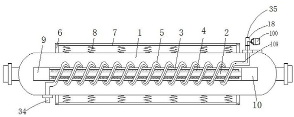
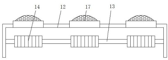
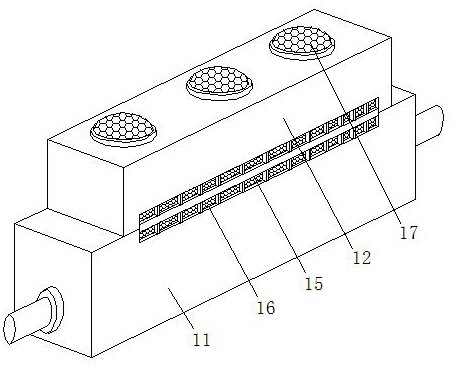
Double-suspension liquid-cooling impact-resistant carbon dioxide laser
A carbon dioxide and impact-resistant technology, applied in the direction of lasers, laser parts, laser parts, etc., can solve the problems of low cooling efficiency of water-cooled tubes, restrictions on the need for outdoor engineering applications, etc., to improve structural stability and use accuracy, release The effect of long heating time and reduced usage
- Summary
- Abstract
- Description
- Claims
- Application Information
AI Technical Summary
Problems solved by technology
Method used
Image
Examples
specific Embodiment 2
[0055] Such as Figure 7 As shown, the others are the same as the first embodiment, the difference is that the internal structure of the circulation output casing 306 in the cooling cavity 311 of the refrigerator 30 is different;
[0056] The interior of the cooling chamber 311 is provided with two side-by-side circulation output casings 306. The cooling chamber 311 forms two low-pressure regions and two high-pressure regions. The two circulation output housings 306 correspond to the gear sets of the heat dissipation motor output shaft 303. The two side-by-side circulation output housings 306 can make the refrigerator 30 use one main and one backup to ensure the normal operation of the cooling system. When the descent is not ideal, it is fully opened to accelerate the circulation of non-Newtonian fluid coolant.
specific Embodiment 3
[0058] Such as Figure 8As shown, the others are the same as the first embodiment, the difference is that the internal structure of the circulation output housing 306 in the cooling chamber 311 of the refrigerator 30 is different; the interior of the cooling chamber 311 is provided with two parallel circulation output housings 306 connected in series , the cooling cavity 311 forms a low-pressure zone, a pressurized zone and a high-pressure zone, the outlet of the high-pressure zone outputs non-Newtonian fluid coolant through the coolant outlet joint 35, and the two circulation output shells 306 are correspondingly installed with the cooling motor output shaft 303 The gear set and the serial circulation output casing 306 enable the non-Newtonian fluid coolant to achieve secondary boost during the output process, increase the output pressure to ensure the fluid flow pressure, and then realize rapid cooling.
specific Embodiment 4
[0060] Such as Figure 9 As shown, the others are the same as in Embodiment 1, the difference is that the internal structure of the circulation output casing 306 in the cooling cavity 311 of the refrigerator 30 is different; the inside of the cooling cavity 311 is provided with a circulation output casing 306, and the cooling cavity 311 A low-pressure zone, a high-pressure zone and a stirring device are formed. The outlet of the high-pressure zone outputs non-Newtonian fluid coolant through the coolant outlet joint 35, and the circulation output housing 306 corresponds to a gear set of a cooling motor output shaft 303 installed, and the stirring device It is fixedly connected with the tail end of the output shaft 303 of another heat dissipation motor, and the stirring device can deposit the non-Newtonian fluid coolant while accelerating the convection between its molecules to rapidly cool down.
[0061] In the process of use, by sheathing the outer casing 3 on the outer surfac...
PUM
 Abstract
Description
Claims
Application Information
 - R&D
- Intellectual Property
- Life Sciences
- Materials
- Tech Scout
- Unparalleled Data Quality
- Higher Quality Content
- 60% Fewer Hallucinations
Browse by: Latest US Patents, China's latest patents, Technical Efficacy Thesaurus, Application Domain, Technology Topic, Popular Technical Reports.
© 2025 PatSnap. All rights reserved.Legal|Privacy policy|Modern Slavery Act Transparency Statement|Sitemap|About US| Contact US: help@patsnap.com


