
Traction wheel and threading machine comprising traction wheel

A technology of traction wheel and threading machine, applied in the field of threading machine, can solve the problems that have not been paid attention to and solved, and achieve the effect of reducing traction, reducing cost and improving threading efficiency

Inactive Publication Date: 2020-11-17
张世祥
View PDF6 Cites 0 Cited by
  • Summary
  • Abstract
  • Description
  • Claims
  • Application Information

AI Technical Summary

Problems solved by technology

[0005] In people's inherent thinking, most people think that the smoother the threading, the better the effect, and most of the research directions of the threading machine focus on improving the stability and speed. The above thread jamming problem has not attracted people's attention and solution

Method used


Image

  • Traction wheel and threading machine comprising traction wheel
  • Traction wheel and threading machine comprising traction wheel
  • Traction wheel and threading machine comprising traction wheel

Examples


Embodiment 1

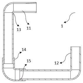
[0039] figure 1 It is a schematic cross-sectional view of the embedded pipe with multiple 90° straight bends and connecting pipes. There are many wiring pipes 11 and 12 in the embedded pipe 1 of the building wall, and the multiple wiring pipes 11 and 12 themselves have a plurality of 90° straight angles 13, and the wiring pipes 11 and 12 are formed at the 90° straight angle. A connecting pipe 14 is connected, and the inner diameter of the connecting pipe 14 is greater than or equal to the outer diameter of the connected pipe. Here, a variable section 15 is formed. When the lead wire is bent through a 90° straight angle, it is particularly easy to get stuck in the variable section. Department 15.

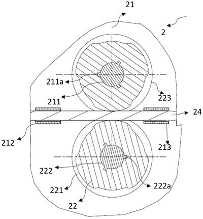
[0040] Such as figure 2 As shown, firstly, this embodiment provides a traction wheel 22 , at least one protruding feature 221 is provided on the outer edge of the traction wheel 22 , and the threading wire 24 is driven by the protruding feature 221 to make intermittent movements. ...

Embodiment 2

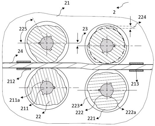
[0048] The features of this embodiment that are the same as those of Embodiment 1 will not be described in detail. The features of this embodiment that are different from Embodiment 1 are: image 3 As shown, in this embodiment, two sets of front and rear transmission assemblies (only the output shaft 211 is shown) are arranged in the frame 21, and there are three evenly distributed raised features 221 on the traction wheel 22, each raised feature 221 Width or amplitude 225 is less than or approximately equal to 60°, ie, raised feature 221 is less than or approximately equal to 60°. For example, 58° means that each driving stroke of the traction wheel 22 is less than or approximately equal to the no-load stroke. The output torque of the motor varies with the load, and an impact can be formed when the traction wheel 22 is converted from the no-load stroke to the drive stroke.

[0049] In order to ensure enough disturbance and impact to help the threading wire 24 smoothly pass t...

Embodiment 3

[0052] The same features of this embodiment and the second embodiment will not be repeated, and the different features of this embodiment and the second embodiment are: still the same figure 2 As shown in , in this embodiment, the centers of the two pairs of traction wheels 22 at the front and rear can have an offset distance 23, thereby intensifying the disturbance of the threading wire 24, so that the threading wire 24 can pass through the 90° straight bend angle 13 and the variable section 15 more smoothly.


PUM


Abstract

The invention discloses a traction wheel and a threading machine comprising the traction wheel, and belongs to the technical field of building electromechanics, the traction wheel comprises a tractionwheel body, the outer edge of the traction wheel body is provided with at least one protruding feature, and the protruding feature drives a threading wire to do intermittent motion; the threading machine comprises a motor and a machine frame, a transmission assembly is arranged in the machine frame, the motor drives the transmission assembly, the traction wheel is arranged on the machine frame, the transmission assembly drives at least one traction wheel, and the traction wheels can abut against a threading wire and drive the threading wire to move. According to the technical scheme, disturbance and impact movement is added to stable movement of the threading wire through intermittent movement, so that the threading wire more easily passes through the 90-degree straight bend and the variable cross section of the connecting pipe, meanwhile, traction force required for pulling the threading wire with the same length is greatly reduced, the number of traction systems can be reduced, threading efficiency is improved, and the threading cost is reduced.

Description

technical field [0001] The invention relates to the field of construction electromechanical technology, in particular to a traction wheel and a threading machine including the traction wheel. Background technique [0002] At present, in building construction, wires are not laid directly but are laid in pre-buried pipes to prevent moisture and heat dissipation, prevent damage to the insulation layer, avoid fires caused by short circuits, and facilitate later maintenance and replacement. Compared with the traditional artificial pre-embedded pipe threading process, the use of threading machine threading avoids the shortcomings of long time-consuming manual threading and low work efficiency. [0003] Most of the threading machines on the market now use a motor to drive the movement of the transmission assembly on the frame, and use the transmission assembly to drive the movement of the threading wire, so that the threading wire passes through the embedded pipe, so that the wire ...

Claims


Application Information

Patent Timeline
IPC IPC(8): H02G1/08
CPCH02G1/088
Inventor 张世祥孙建东
Owner 张世祥
Learn More