
Wear-resistant rotatable broadband electromagnetic shielding structure, design method and application

A technology of electromagnetic shielding structure and design method, applied in the fields of magnetic field/electric field shielding, electrical components, metal containers, etc., can solve the problems of non-contact structure lack of mechanical and structural support, unstable rotation, inability to achieve broadband electromagnetic shielding, etc. To achieve good structure and mechanical support characteristics, the effect of smooth rotation

Active Publication Date: 2020-11-17
XIDIAN UNIV
View PDF23 Cites 2 Cited by
  • Summary
  • Abstract
  • Description
  • Claims
  • Application Information

AI Technical Summary

Problems solved by technology

However, the structure of the choke slot depends on the quarter-wavelength conversion structure, so it is a narrow-band structure, which cannot realize broadband electromagnetic shielding, and the non-contact structure lacks sufficient mechanical and structural support at the contact part
Second, the contact structure of brushes or shrapnel, which uses brushes or shrapnel to achieve electromagnetic shielding during rotation, but this type of structure is a contact structure, and there will be additional frictional resistance in the rotating part during rotation, which is subject to manufacturing and Influenced by the assembly process, in practice, it will lead to uneven resistance of the contact parts, which will cause unstable rotation
[0005] (1) The non-contact electromagnetic shielding structure of the choke slot supporting the rotation characteristic cannot realize broadband electromagnetic shielding, and the non-contact structure lacks sufficient mechanical and structural support
[0006] (2) The existing contact electromagnetic shielding structure supporting the rotation characteristic has the problems of wear and unstable rotation
[0008] For rotating or movable electromagnetic structures, hard connection structures cannot be used in their rotating or movable parts. If sufficient electromagnetic shielding characteristics cannot be guaranteed while the structure is movable and rotatable, it will seriously affect the relevant microwave and millimeter wave flexible mechanisms and Component performance
For this type of rotating structure, if a simple non-contact structure is used, the non-contact structural gap will cause electromagnetic leakage and affect the electromagnetic shielding effect; if a choke groove non-contact structure is used, although a certain degree of electromagnetic shielding can be achieved, However, the electromagnetic shielding characteristics of broadband cannot be realized, and the working bandwidth is limited in practical applications; although the existing contact structure can realize electromagnetic shielding of broadband, there will be problems of wear and unstable rotation
How to achieve excellent structural performance, stable rotation, broadband electromagnetic shielding characteristics, and anti-wear performance is a difficult point in this technology. So far, there is no effective solution

Method used


Image

  • Wear-resistant rotatable broadband electromagnetic shielding structure, design method and application
  • Wear-resistant rotatable broadband electromagnetic shielding structure, design method and application
  • Wear-resistant rotatable broadband electromagnetic shielding structure, design method and application

Examples


Embodiment 2

[0074] Embodiment 2: The waveguide rotary joint adopting the anti-wear and rotatable broadband electromagnetic shielding structure of the present invention

[0075] A waveguide rotary joint based on the anti-wear and rotatable broadband electromagnetic shielding structure of the invention. A coaxial transmission line is constructed inside the columnar base of the wear-resistant and rotatable broadband electromagnetic shielding structure of the present invention for transmitting electromagnetic signals, combined with the structure of the present invention, a rotatable coaxial transmission transition section is formed. According to the design method of the wear-resistant and rotatable broadband electromagnetic shielding structure of the present invention, the key dimension parameters of the electromagnetic shielding structure are obtained to ensure that the electromagnetic shielding bandwidth of the rotating part of the coaxial transition section covers the operating frequency ra...


PUM


Abstract

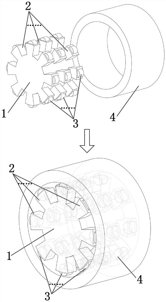
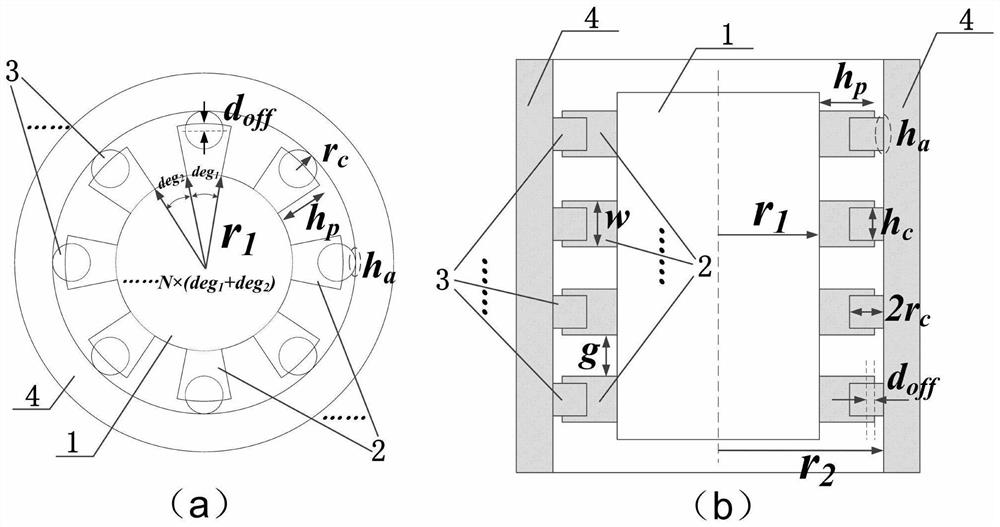
The invention belongs to the technical field of microwave and millimeter wave rotation and flexible mechanisms, and discloses an anti-wear rotatable broadband electromagnetic shielding structure, a design method and application, a plurality of arc surface metal convex bodies with the same radius are periodically and regularly arranged along the outer cylindrical surface of a cylindrical substrateto form an array structure, and an embedded ball is arranged at the upper part of each metal convex body. A cylindrical cavity is formed in the shielding body, the cylindrical cavity and the cylindrical surface arc of the cylindrical base body are in a concentric circle relation, proper size parameters are determined through specific steps, the arc surface metal convex body array and the embeddedballs are combined and then inserted into the cylindrical cavity of the shielding body, and a contact structure is formed in a clearance fit mode. And the metal convex body array, the embedded balls and the cylindrical cavity jointly form an electromagnetic band gap structure with a wide electromagnetic forbidden band, so that broadband electromagnetic shielding is realized. The electromagnetic shielding structure disclosed by the invention has a rotatable characteristic, has wear resistance under a proper size condition, and realizes broadband electromagnetic shielding of a microwave and millimeter wave circuit and structure during rotation and movement.

Description

technical field [0001] The invention belongs to the technical field of microwave and millimeter wave rotation and flexible mechanisms, and in particular relates to an anti-wear and rotatable broadband electromagnetic shielding structure, design method and application. Background technique [0002] At present, in various microwave and millimeter wave rotary and flexible mechanisms, such as rotary joints, flexible joints, and rotary switches, it is very important to ensure the function and performance of circuit components while maintaining normal electromagnetic shielding performance while rotating and moving the structure. For example, the rotary joints widely used in radar cannot use hard contact for the rotating parts. An electromagnetic shielding structure with rotatable characteristics must be used to prevent electromagnetic signals from leaking and coupling from the rotating parts, so as to ensure good electromagnetic transmission performance of the rotating joints. [...

Claims


Application Information

Patent Timeline
Patent Type & Authority Applications(China)
IPC IPC(8): H05K9/00
CPCH05K9/0049H05K9/006
Inventor 陈翔孙冬全崔万照李小军
Owner XIDIAN UNIV
Learn More