
Heat insulation pouring ladle with ladle lining push-out device

A technology for pushing out devices and pouring ladles, which is applied in the direction of casting melt containers, metal processing equipment, casting equipment, etc., can solve the problems of long cycle of pouring ladles and the inability of heat preservation of pouring ladles to meet the process requirements, etc., to achieve increased speed and improved Insulation performance, to meet the effect of rapid production

Inactive Publication Date: 2020-11-20
TIANJIN NEW WEISAN INDS
View PDF8 Cites 2 Cited by
  • Summary
  • Abstract
  • Description
  • Claims
  • Application Information

AI Technical Summary

Problems solved by technology

[0004] The object of the present invention is to provide a thermal insulation pouring ladle with a lining push-out device to solve the technical problems that the thermal insulation of the pouring ladle cannot meet the process requirements and the cycle period of the pouring ladle is long

Method used


Image

  • Heat insulation pouring ladle with ladle lining push-out device
  • Heat insulation pouring ladle with ladle lining push-out device
  • Heat insulation pouring ladle with ladle lining push-out device

Examples


Embodiment Construction

[0026] In order to better understand the purpose, structure and function of the present invention, a kind of thermal insulation pouring bag with a lining push-out device of the present invention will be described in further detail below in conjunction with the accompanying drawings.

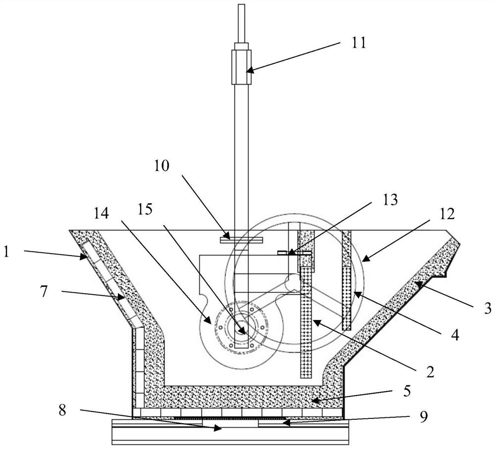
[0027] Such as Figure 1-Figure 4 As shown, the present invention includes: a cladding 1, a cladding beam 11 arranged on the cladding 1, wherein, both sides of the cladding 1 are respectively provided with a cladding shaft 15 in a shaft-hole connection mode, and a cladding shaft 15 is adopted on the cladding shaft 15. The shaft hole connection mode is respectively equipped with a vertical pole, and a cladding beam 11 is installed between the upper ends of the two poles. A cladding buckle 10 is arranged on the pole on one side of the cladding beam 11, and a cladding buckle 10 on the side of the cladding buckle 10 is provided. The shell shaft 15 is connected with the reducer 14, and the reducer 14 ...


PUM


Abstract

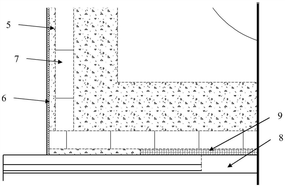
The invention discloses a heat insulation pouring ladle with a ladle lining push-out device. The heat insulation pouring ladle comprises a ladle shell and a ladle beam arranged on the ladle shell. Thetwo sides of the ladle shell are each provided with a ladle shell shaft, vertical rods are mounted on the ladle shell shafts, and the ladle beam is mounted on the vertical rods. The ladle shell shafts are connected with a speed reducer, and a ladle wheel is mounted on the speed reducer. A ladle nozzle is arranged on the upper edge and the edge of the ladle shell, and a primary slag blocking brickis arranged between the interior of a cavity of the ladle shell and the ladle nozzle. A communicating ladle nozzle runner is arranged along the edge of the inner side of the ladle shell, and a secondary slag blocking brick is arranged on the upper portion of the ladle nozzle runner. A heat insulation layer is further arranged between the side wall of the ladle shell and the ladle nozzle and refractory matter, and heat insulation brick layers are arranged in the position, on the ladle shell, of the refractory matter and in the position, at the bottom of the ladle shell, of the refractory matter to achieve heat insulation. The ladle wheel is rotated, so that molten steel flows out from the bottom of the ladle shell along the ladle nozzle runner. By means of the heat insulation pouring ladle, the heat insulation performance of the pouring ladle is improved; and after the pouring ladle which is just offline is cooled, a ladle lining can be dismounted, and the speed of dismounting the ladle lining is increased.

Description

technical field [0001] The invention belongs to the field of mechanical casting, and in particular relates to a thermal insulation pouring ladle with a lining push-out device. Background technique [0002] At present, with the rapid development of science and technology, the production efficiency of the production line is also constantly improving, and the production process requirements are also more stringent, which narrows the pouring temperature range; because the pouring line is poured, although the pouring ladle has a form of heat preservation However, there is still a phenomenon that the average temperature of the molten steel drops by about 10°C per minute in the pouring ladle. The normal temperature range of pouring is exceeded, so it cannot meet the process requirements. [0003] When the pouring ladle is off-line, the lining of the pouring ladle needs to be cooled first, and then manually removed; since the cooling time is more than 4 hours, and it takes about 2 ...

Claims


Application Information

Patent Timeline
Patent Type & Authority Applications(China)
IPC IPC(8): B22D41/02
CPCB22D41/026
Inventor 陈友三陈常彬林政德王金辉张振东翟永杰石晓菊焦晨阳
Owner TIANJIN NEW WEISAN INDS
Learn More