Eureka AIR delivers breakthrough ideas for toughest innovation challenges, trusted by R&D personnel around the world.

Welding method for central nozzle flange and nozzle corrugated pipe body of 300MW-level gas turbine

A center nozzle and welding method technology, applied in welding equipment, auxiliary devices, metal processing, etc., can solve problems such as welding deformation, uneven rebound force, nozzle eccentricity, etc.

Active Publication Date: 2020-11-20
HARBIN TURBINE +1
View PDF5 Cites 3 Cited by
  • Summary
  • Abstract
  • Description
  • Claims
  • Application Information

AI Technical Summary

Problems solved by technology

[0003] The purpose of the present invention is to solve the problem that the compression of the bellows in the existing brazing assembly process leads to the formation of uneven rebound force and the severe eccentricity of the nozzle. Stress is generated inside the material, which leads to a particularly serious problem of welding deformation, and then provides a welding method for the center nozzle flange of the 300MW gas turbine and the nozzle bellows body

Method used


Image

  • Welding method for central nozzle flange and nozzle corrugated pipe body of 300MW-level gas turbine
  • Welding method for central nozzle flange and nozzle corrugated pipe body of 300MW-level gas turbine
  • Welding method for central nozzle flange and nozzle corrugated pipe body of 300MW-level gas turbine

Examples


specific Embodiment approach 1

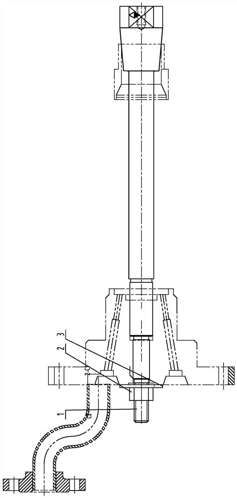
[0023] DETAILED DESCRIPTION One: Combination Figure 1 - Figure 4 The present embodiment described embodiment, the present embodiment the one-stage combustion engine 300MW center nozzle flange welded bellows and the nozzle, the method is implemented in accordance with what the steps:

[0024] A step of welding cyclone: ​​one end of the bellows and the nozzle end of the nozzle and swirler assembly bellows welded and fixed to the outer housing, to ensure that the nozzle is arranged coaxially with the bellows of the bellows and the nozzle outer shell;

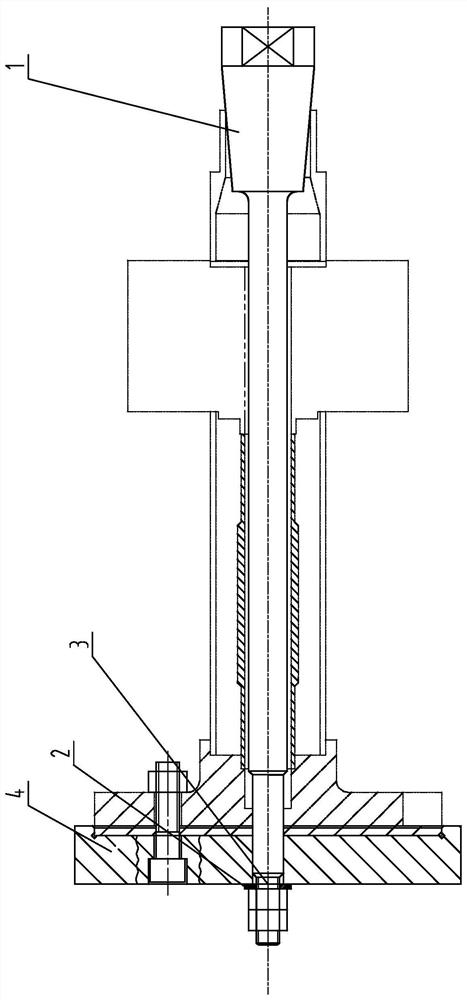
[0025] Step two, the mounting assembly and welding nozzle swirler positioned tooling: positioning the nozzle swirler assembly and welding fixture attached to the nozzle of the bellows and the nozzle housing outer bellows, the bellows and the other end of the nozzle center of the nozzle is inserted in the corresponding flange the grooves, the nozzle and the other end of the bellows is inserted into the outer casing corresponding to the ...

specific Embodiment approach 2

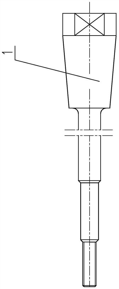
[0031] DETAILED DESCRIPTION 2: Combination figure 2 and image 3 DESCRIPTION present embodiment, a 300MW class gas turbine nozzles with a central nozzle flange welded bellows method, the procedure two nozzle swirler assembly and welding fixture includes positioning a positioning rods, tighten the nut 2 and the washer 3 positioning lever 1 is stepped rod, the positioning lever right end to end portion of the workpiece 1 has a conical body, the positioning rod left processing 1 is externally threaded positioning rod 1 the end of the cone to the outer threaded end sequentially a bellows defining portion, defining a first coaxial portion and a second portion defining coaxially, successively positioning rod 1 inserted in the swirler assembly, and the central nozzle bellows nozzle flange, the positioning rod having a tapered conical surface in vitro in the top cyclone 1 on assembly, the bellows unit defining a nozzle inserted in the bellows portion and defining a first coaxial portion de...

specific Embodiment approach 3

[0032] Specific Embodiment 3: Combination figure 1 DESCRIPTION present embodiment, a central nozzle flange 300MW gas turbine stage and a welding method, tooling positioning the nozzle body shaft equal to the diameter of the bellows with the bellows inner diameter of the outer nozzle portion defines a bellows 1, defining a first coaxial portion an outer diameter equal to the inner diameter of the central nozzle and the corresponding flange of the mounting hole, and an outer diameter corresponding to the central portion defining a second coaxial nozzle equal to the inner flange mounting holes, and other specific embodiments an identical.


PUM


Abstract

The invention discloses a welding method for a central nozzle flange and a nozzle corrugated pipe body of a 300MW-level gas turbine, and relates to a corrugated pipe body welding method. The welding method aims to solve the problems that a corrugated pipe is compressed in the existing brazing assembly process, so that non-uniform rebound force is formed by the corrugated pipe, and a nozzle is seriously eccentric; and in a nozzle body laser welding structure, a base material is a thin-wall part, uneven and rapid heat input causes stress to be generated in the material, and welding deformation is particularly serious. The welding method comprises the steps that S1, a swirler is welded; S2, a nozzle swirler assembly welding positioning tool is installed; S3, brazing filler metal is added; S4,positioning and pressing are carried out; S5, the coaxiality is checked; S6, welding and fixing are carried out; S7, vacuum brazing is carried out, specifically, a gas turbine nozzle assembly fixed in the sixth step is fed into a vacuum heat treatment furnace to be subjected to vacuum brazing. The welding method can used for welding the corrugated pipe body.

Description

Technical field [0001] The present invention relates to a method of welding a bellows body, particularly relates to a gas turbine stage 300MW center nozzle flange welded bellows and nozzle method. Background technique [0002] 300MW stage heavy duty gas turbine nozzle assembly integrally connected mainly in the form of solder made of, which involves laser welding the welder content, gold-based brazing and vacuum brazing. Now mainly affect the overall accuracy of the nozzle assembly and welding produced the following points: 1. In the brazing assembly process, resulting in structural design the bellows inside the nozzle assembly in a compressed state, resulting in an uneven own repulsive force and cause serious eccentric nozzle Case. Laser welding nozzle body 2. Because the structure of 3mm plurality of thin stainless steel substrate member, by welding temperature field effect rapid heat input causes uneven stresses inside the material, and the thin-walled member itself not rigid ...

Claims


Application Information

Patent Timeline
IPC IPC(8): B23K1/008B23K3/00B23K3/08
CPCB23K1/008B23K3/00B23K3/087
Inventor 隋妍安天成王吉祥武尚尚邵苓储继影于华张仁军孙柏慧王乾王岩
Owner HARBIN TURBINE
Why Eureka
Eureka Blog
Learn More