
Special fixture for numerical control machining center

A special fixture and machining center technology, applied in the direction of manufacturing tools, metal processing equipment, metal processing machinery parts, etc. To ensure the stability of clamping and other issues, to achieve the effect of stable clamping, convenient operation and reducing surface damage

Inactive Publication Date: 2020-11-20
JIANGSU SECURITY TECH CARRER ACADEMY
View PDF6 Cites 3 Cited by
  • Summary
  • Abstract
  • Description
  • Claims
  • Application Information

AI Technical Summary

Problems solved by technology

[0003] However, the clamps currently used in CNC machining cannot clamp workpieces with irregular shapes, and they cannot well avoid pinching products while ensuring stability, and at the same time cannot guarantee well on the basis of avoiding pinching products. clamping stability

Method used


Image

  • Special fixture for numerical control machining center
  • Special fixture for numerical control machining center
  • Special fixture for numerical control machining center

Examples


Embodiment Construction

[0030] Attached below Figure 1 to Figure 3 , a specific embodiment of the present invention will be described in detail, but it should be understood that the protection scope of the present invention is not limited by the specific embodiment.

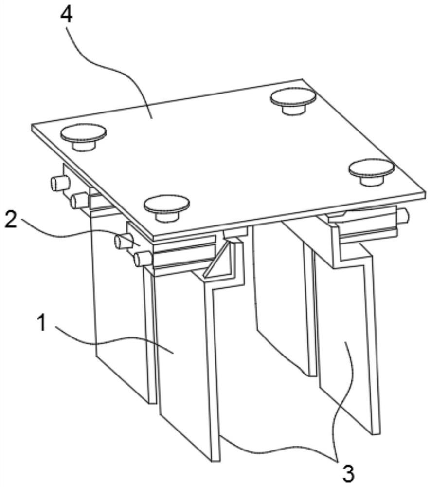
[0031] Such as figure 1 As shown, the embodiment of the present invention provides a special fixture for CNC machining center, including:

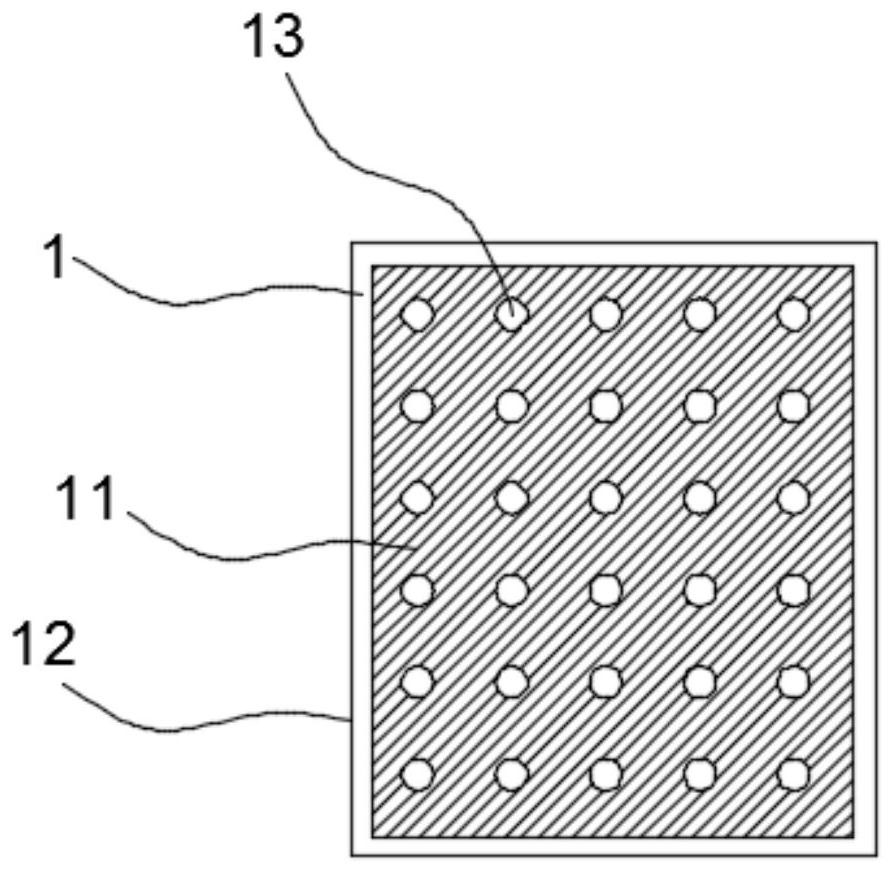
[0032] A fixed plate 4 arranged horizontally; the bottom of the fixed plate 4 is provided with a clamping assembly 3, the clamping assembly 3 includes two vertical and opposite clamping plates 1, and one end of the clamping plate 1 slides through the guide structure and the fixed plate 4 connected, the two clamping plates 1 can move towards each other along the guide structure, and the opposite sides of the two clamping plates 1 are evenly arranged with a plurality of clamping parts.

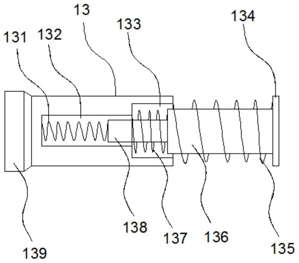
[0033] Wherein, the clamping part includes a fixed seat 139, and the fixed seat 139 is fixed with the clamping p...


PUM


Abstract

The invention discloses a special fixture for a numerical control machining center. The special fixture comprises a fixing plate, wherein a clamping assembly is arranged at the bottom of the fixing plate; the clamping assembly comprises two clamping plates vertically and oppositely arranged; one end of each clamping plate is slidably connected with the fixing plate through a guide structure; the two clamping plates can move towards each other along the guide structures; a plurality of clamping parts are uniformly distributed on the opposite sides of the two clamping plates, wherein each clamping part comprises a fixing seat, and the fixing seats are fixed to the clamping plates; one surfaces, away from the clamping plates, of the fixing seats are connected with contact parts; a multi-stagebuffer structure is arranged between each contact part and the corresponding fixing seat; the bottom of the fixing plate is further provided with a plurality of telescopic devices; and the telescopicends of the telescopic devices are connected with one sides, opposite to each other, of the two clamping plates. The special fixture is simple in structure and convenient to operate, can clamp workpieces of different shapes on the premise of ensuring stable clamping, avoids clamping damage on the surfaces of the workpieces, and is worth popularizing.

Description

technical field [0001] The invention relates to the field of mechanical fixtures, in particular to a special fixture for a numerically controlled machining center. Background technique [0002] Numerical control machining (numerical control machining) refers to a process method for processing parts on a numerical control machine tool. The process regulations of numerical control machine tool machining and traditional machine tool machining are generally consistent, but significant changes have also taken place. A machining method that uses digital information to control the movement of parts and tools. It is an effective way to solve the problems of variable variety, small batch, complex shape and high precision of parts and realize high-efficiency and automatic processing. CNC machining refers to the processing that the control system issues instructions to make the tool perform various movements that meet the requirements, and express the technical requirements and proces...

Claims


Application Information

Patent Timeline
Patent Type & Authority Applications(China)
IPC IPC(8): B23Q3/00
CPCB23Q3/00B23Q2703/04
Inventor 伏彩建陈发金董宏伟赵海彬倪磊金银
Owner JIANGSU SECURITY TECH CARRER ACADEMY
Learn More