Heat pipe type photo-thermal energy storage heating system

A heating system, heat pipe technology, applied in the field of heat pipe solar thermal energy storage heating system, can solve the problem of large energy consumption and achieve the effect of saving consumption

Pending Publication Date: 2020-11-20
ZHENJIANG XINMENGXI ENERGY TECH
View PDF0 Cites 0 Cited by
  • Summary
  • Abstract
  • Description
  • Claims
  • Application Information

AI Technical Summary

Problems solved by technology

The heating equipment of the existing floor heating system is generally large-scale self-heating boiler, wall-hung boiler, gas furnace, electric control infrared equipment, etc., which consume a lot of energy

Method used


Image

  • Heat pipe type photo-thermal energy storage heating system

Examples


Embodiment Construction

[0014] In order to deepen the understanding of the present invention, the present invention will be further described below in conjunction with the embodiments and accompanying drawings. The embodiments are only used to explain the present invention and do not constitute a limitation to the protection scope of the present invention.

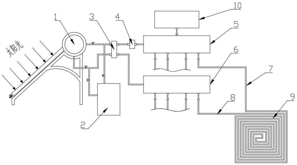
[0015] Such as figure 1 As shown, a heat pipe type photothermal energy storage heating system includes solar heating equipment 1, auxiliary heating equipment 2, water mixing valve 3, circulation pump 4, water separator 5, water collector 6, and water inlet pipe 7 , return pipe 8, floor heating system 9 and water supply system 10.

[0016] A heat pipe type photothermal energy storage heating system, including solar heating equipment 1, the solar heating equipment 1 includes a hot water pipe and a cold water pipe, a circulation pump 4 is arranged on the hot water pipe, and a water separator is arranged behind the circulation pump 4 5. One end of t...


PUM


Abstract

The invention discloses a heat pipe type photo-thermal energy storage heating system. The heat pipe type photo-thermal energy storage heating system involves solar heat supply equipment, wherein the solar heating equipment comprises a hot water pipe and a cold water pipe, a circulating pump is arranged on the hot water pipe, a water segregator is arranged behind the circulating pump, one end of the water segregator is connected with a water supply system, the other end of the water segregator is connected with a water inlet pipe of a floor heating system, a water return pipe of the floor heating system is connected with a water collector, the water collector is connected with the cold water pipe of the solar heat supply equipment, a water mixing valve is arranged between the hot water pipeand the cold water pipe, and auxiliary heat supply equipment is arranged on a pipeline between the solar heat supply equipment and the water mixing valve. The heat pipe type photo-thermal energy storage heating system is ingenious in design, adopts solar energy as an energy source of the floor heating system, reduces fossil fuel consumption, and is green and environmentally friendly; and the auxiliary heat supply equipment is additionally arranged and can replace the floor heating system to supply heat when the sun is not good.

Description

technical field [0001] The invention relates to a heat pipe type photothermal energy storage heating system. Background technique [0002] After more than 20 years of development, floor radiant heating has gradually replaced the ancient heating methods of radiators and light radiators, and has become a new heating equipment for modern families. Various floor heating water separators and temperature control valves have also begun to be widely used in our in daily life. Floor radiant heating is an advanced heating method. Its working principle is to feed circulating hot water into the heating pipe loop under the laid floor or floor tiles or directly lay heating cables to heat the floor. The heat passes through a large area of ​​the ground, mainly It radiates gently and evenly to the space above the floor, making the human body feel the dual heat effect of heat radiation and air temperature. The heating equipment of the existing floor heating system is generally large-scale s...

Claims


Application Information

Patent Timeline
Patent Type & Authority Applications(China)
IPC IPC(8): F24D11/00F24D19/10F24S10/95F24S80/30
CPCF24D11/003F24D19/1042F24S10/95F24S80/30Y02B10/20Y02B10/70Y02E10/44
Inventor 王坤
Owner ZHENJIANG XINMENGXI ENERGY TECH
Why Eureka
Try Eureka