
Automatic zooming thin-film liquid lens based on temperature control and preparation method

A liquid lens, automatic zoom technology, applied in the lens, optics, instruments and other directions, can solve the problems of increasing the difficulty of device preparation, complex process preparation, small clear aperture, etc., to increase the degree of system integration, simple and convenient operation, and reduce Small volume effect

Active Publication Date: 2020-11-20
NORTHWESTERN POLYTECHNICAL UNIV
View PDF2 Cites 8 Cited by
  • Summary
  • Abstract
  • Description
  • Claims
  • Application Information

AI Technical Summary

Problems solved by technology

However, this kind of lens has the following problems: the process preparation is relatively complicated, the control voltage is high, and the aperture is small.
The conventional process has the following problems: (1) The open channel of the process requires a subsequent packaging process, and usually forms a channel with a rectangular cross section, which increases the difficulty of device preparation
(2) The process needs to be exposed, developed, and molded in an ultra-clean environment, and the experimental cost is high and time-consuming
(3) The traditional process is limited to the preparation of 2D plane structures
If channels for 3D structures need to be fabricated, individual molded layers need to be stacked and bonded to multiple PDMS structures, which is time-consuming and requires precise alignment

Method used


Image

  • Automatic zooming thin-film liquid lens based on temperature control and preparation method
  • Automatic zooming thin-film liquid lens based on temperature control and preparation method
  • Automatic zooming thin-film liquid lens based on temperature control and preparation method

Examples


Embodiment Construction

[0041] Now in conjunction with embodiment, accompanying drawing, the present invention will be further described:

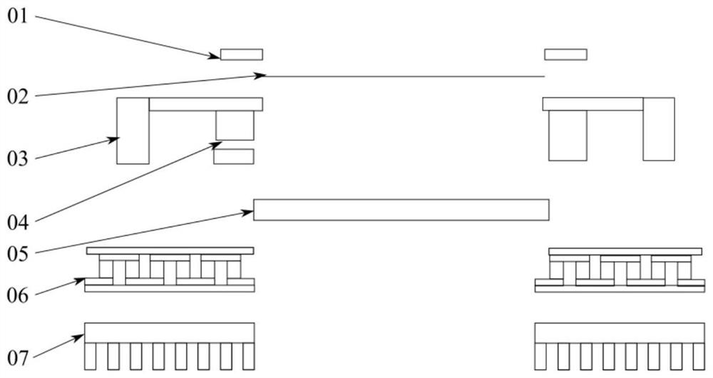
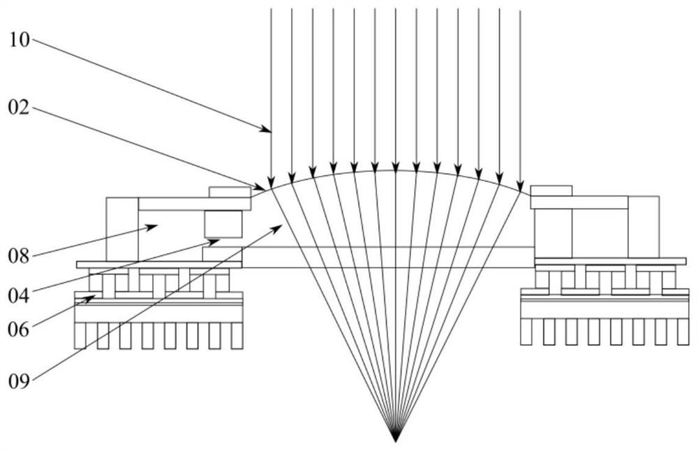
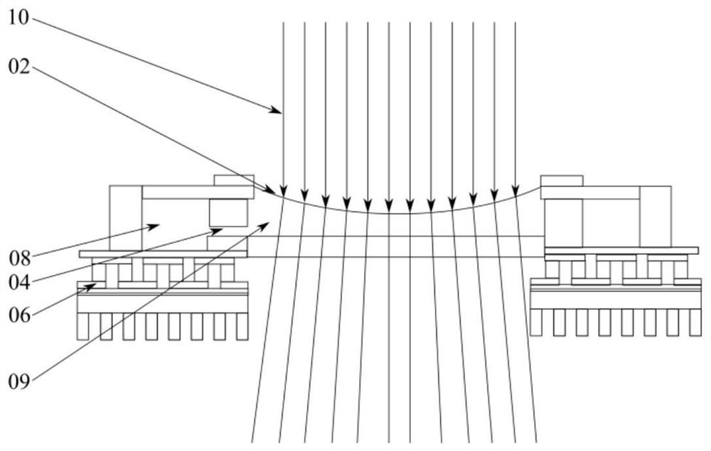
[0042] (1) The present invention proposes an automatic zoom liquid lens. as attached figure 1 As shown, the thin film liquid lens includes: thin film, optical liquid, 3D printed microchannel, micro cooling / heating sheet, and heat dissipation substrate. Using the principle of heat-gas drive, when the cooling plate is heated or cooled, the movement speed of the air molecules in the closed cavity is changed, which in turn causes a volume change, and finally controls the movement of a small amount of liquid in the closed cavity, causing the deformation of the film and realizing the automatic zoom optical lens.

[0043] (2) At normal temperature and pressure, air can be approximated as an ideal gas. The state of an ideal gas of a certain mass can be described by three state parameters P, V, T. And if any two of the parameters are determined, the third parameter mus...


PUM

PropertyMeasurementUnit
thicknessaaaaaaaaaa
lengthaaaaaaaaaa
transparencyaaaaaaaaaa

Abstract

The invention relates to an automatic zooming thin-film liquid lens based on temperature control and a preparation method. An optical thin-film structure is located between a circular hole structure and a micro-channel, a transparent glass sheet is located between the micro-channel and a semiconductor chilling plate, and a heat sink structure is arranged at the lower end of the semiconductor chilling plate; an air cavity is formed in the micro-channel and is communicated with an air outlet in the side wall of the micro-channel; and an optical liquid cavity is formed between the optical thin-film structure and the transparent glass sheet, and a micro-channel structure is arranged between the air cavity and the optical liquid cavity and is communicated with a liquid inlet in the side wall ofthe micro-channel. The precise focusing function of the thin-film liquid lens is achieved, the volume of air is changed by controlling the temperature of the air in the sealed space, so that the thinfilm expands upwards or sinks inwards, and finally the convergence or divergence effect on light rays is achieved. The liquid lens has the functions of a concave lens and a convex lens at the same time, and the focal length is continuously adjustable.

Description

technical field [0001] The invention belongs to the field of thin-film liquid lenses, and relates to an automatic zoom thin-film liquid lens based on temperature control and a preparation method thereof, more specifically, relates to a method for controlling the temperature, pressure and volume of gas in a sealed cavity to drive Liquid flow, thin-film liquid lens for automatic zooming and liquid lens array of related design. Background technique [0002] Liquid lenses use liquid materials as optical materials, and can realize the zoom function by controlling the curvature of the liquid interface or changing the refractive index of the liquid. Compared with auto-focus lenses, liquid lenses have the advantages of small size and fast response because of the lack of moving mechanical structures. Wide range of applications. [0003] Liquid lenses are mainly divided into liquid crystal lenses, electrowetting lenses, thin film liquid lenses and other types. The birefringence eff...

Claims


Application Information

Patent Timeline
Patent Type & Authority Applications(China)
IPC IPC(8): G02B3/14G02B26/00
CPCG02B3/14G02B26/004
Inventor 张维张继巍邸江磊赵建林
Owner NORTHWESTERN POLYTECHNICAL UNIV
Learn More