Multi-channel synchronous low-frequency vibration data acquisition device
A low-frequency vibration and data acquisition technology, applied in general control systems, instruments, computer control, etc., can solve the problems of high maintenance and after-sales service costs, small number of acquisition channels, and large errors in synchronous acquisition, so as to increase maintenance costs and increase Cost, the effect of controlling equipment cost
- Summary
- Abstract
- Description
- Claims
- Application Information
AI Technical Summary
Problems solved by technology
Method used
Image


Examples
Embodiment 1
[0043] The technical solution of the present invention is: the multi-channel synchronous low-frequency vibration data acquisition device is an 8-channel synchronous data acquisition and signal processor, and the structural health diagnosis system can be composed of multiple multi-channel synchronous low-frequency vibration data acquisition according to the requirements of field testing The devices carry out cascade network acquisition. Among these multi-channel synchronous low-frequency vibration data acquisition devices, one device works in the master mode, and the others work in the slave mode, and the synchronization signal is sent out through the master mode for system synchronization acquisition.
[0044] The hardware part of the multi-channel synchronous low-frequency vibration data acquisition device includes analog signal processing and analog-to-digital converters, a central main control CPU, and a data communication system.
[0045] The analog signal processing and an...
Embodiment 2
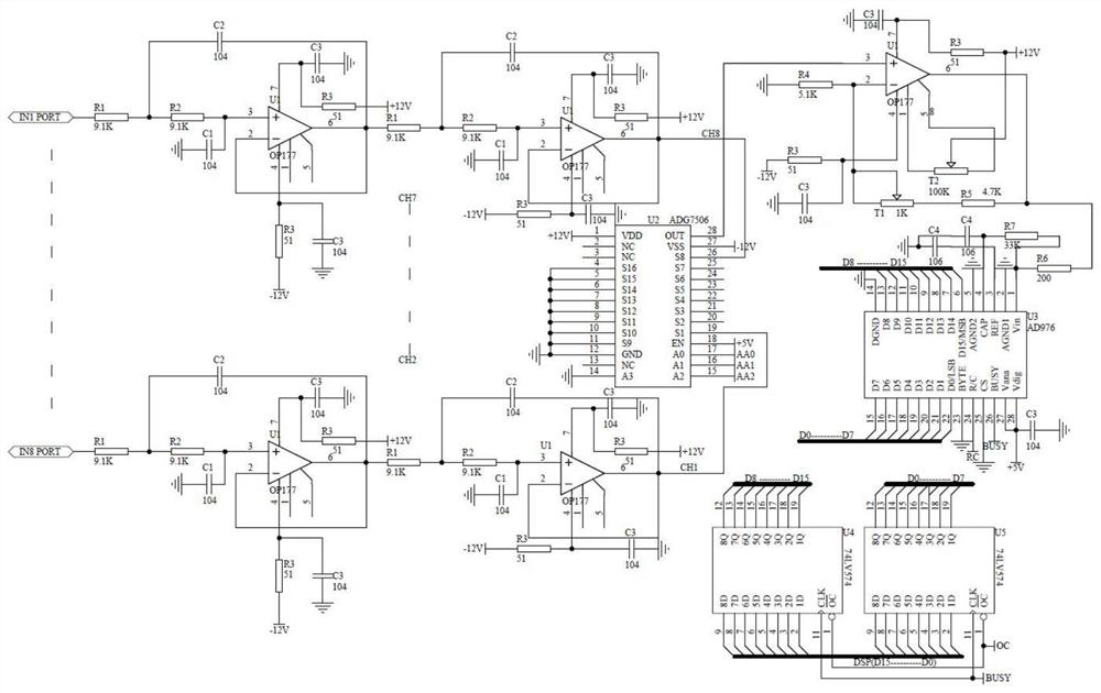
[0069] The specific implementation circuit is as follows figure 1 The analog signal processing and analog-to-digital conversion shown include 8 channels of analog signal processing with the same parameters and configurations, each route is composed of two operational amplifiers U1, and the signal channel is selected through the analog switch U2 and sent to the analog-to-digital conversion chip U3 for conversion. The completed digital signal is sent to data latch U4, U5. Described analog-to-digital signal conversion and data latch comprise analog-to-digital signal converter U2 and data latch U3 and U4, concrete circuit such as figure 2 The central master control CPU includes a DSP digital signal processor and related peripheral circuits, a large-scale logic controller, a synchronous master-slave logic controller, and a DSP digital signal processor and related peripheral circuits include a DSP digital signal processor and related peripheral circuits U6, JTAG emulation debuggin...
Embodiment 3
[0076] A multi-channel synchronous low-frequency vibration data acquisition method, the steps are as follows:
[0077] S1. Using a multi-channel synchronous low-frequency vibration data acquisition device, each analog input has a total of 8 channels, the channel signal is input to the pre-processing module, the input signal is subjected to low-pass filtering twice, and then the signal is input to the analog-to-digital signal converter;
[0078] S2, the analog-to-digital signal converter converts an analog signal into a 16-bit digital signal, and transfers the 16-bit digital signal into the data latch, and simultaneously sends a latch clock signal (BUSY);
[0079] S3. The data latch performs latch processing on the signal.
[0080] Further, the specific steps of the data latch processing signal in step S3 are as follows:
[0081] S3.1 The central main control CPU generates the RC signal for the analog-to-digital converter U3 to start conversion through a large-scale programmab...
PUM
 Abstract
Description
Claims
Application Information