
Machining equipment with automatic positioning structure for circuit board perforating

A technology of automatic positioning and processing equipment, applied in metal processing and other directions, can solve the problems of low degree of automation, waste of production time, etc., and achieve the effect of high degree of automation, convenient drilling of drills, and reduction of processing difficulty

Inactive Publication Date: 2020-11-24
DONGGUAN RONGGONG AUTOMATION TECH CO LTD
View PDF0 Cites 1 Cited by
  • Summary
  • Abstract
  • Description
  • Claims
  • Application Information

AI Technical Summary

Problems solved by technology

[0004] Aiming at the deficiencies of the prior art, the present invention provides a processing equipment with an automatic positioning structure for punching circuit boards, which solves the problem that the general circuit board processing and production device proposed in the above background technology needs to adjust the device system before processing, and the circuit board needs to be adjusted. The board is placed in a designated area to facilitate device processing. Secondly, circuit board processing requires other devices or manual placement and removal of the circuit board. The degree of automation is low, which wastes production time and cannot well meet people's use needs.

Method used


Image

  • Machining equipment with automatic positioning structure for circuit board perforating
  • Machining equipment with automatic positioning structure for circuit board perforating
  • Machining equipment with automatic positioning structure for circuit board perforating

Examples


Embodiment Construction

[0026] The technical solutions in the embodiments of the present invention will be clearly and completely described below in conjunction with the accompanying drawings in the embodiments of the present invention. Obviously, the described embodiments are only some of the embodiments of the present invention, not all of them. Based on The embodiments of the present invention and all other embodiments obtained by persons of ordinary skill in the art without making creative efforts belong to the protection scope of the present invention.

[0027] In the description of the present invention, unless otherwise stated, the meaning of "plurality" is two or more; the terms "upper", "lower", "left", "right", "inner", "outer" , "front end", "rear end", "head", "tail", etc. indicate the orientation or positional relationship based on the orientation or positional relationship shown in the drawings, and are only for the convenience of describing the present invention and simplifying the desc...


PUM


Abstract

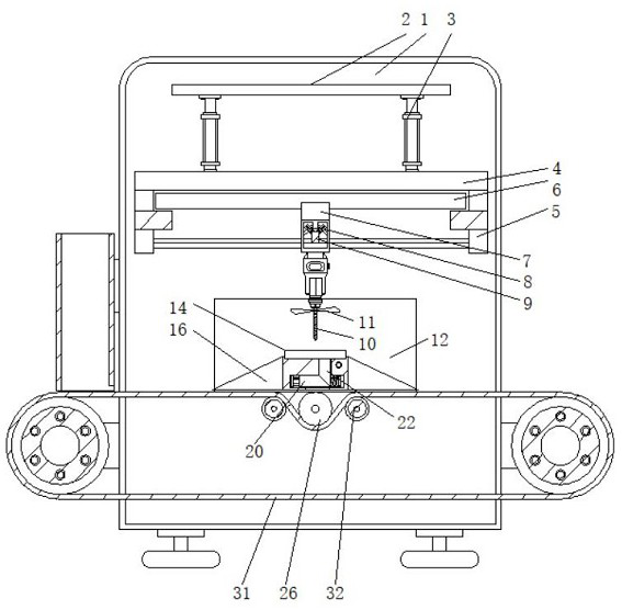
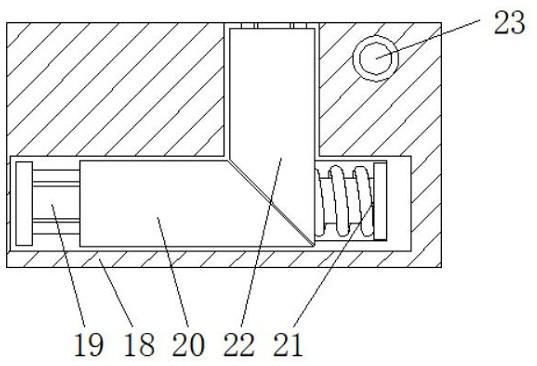
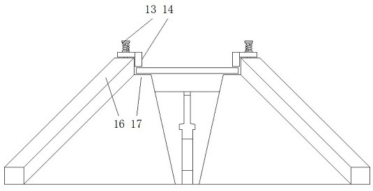
The invention discloses machining equipment with automatic positioning structure for circuit board perforating. The machining equipment comprises a box body and a rack, a top plate is arranged at thefront end of the box body, telescopic rods are arranged at the lower end of the top plate, a longitudinal sliding rail is fixed to the lower ends of the telescopic rods, a transverse rod is arranged at the upper end of the middle of a transverse sliding rail, a pulley is arranged inside a connecting plate, a drill bit is arranged at the lower end of the middle of a longitudinal rod, baffles are connected to the front ends and the rear ends of fan blades, pressing plates are arranged at the lower ends of first springs, limiting plates are arranged at the lower ends of the pressing plates, and collecting plates are arranged at the left ends of the limiting plates. Compared with an existing common circuit board production device, the machining equipment with the automatic positioning structure for circuit board perforating is provided with the automatic positioning structure, only the width between clamping structures of the equipment needs to be adjusted, and an automatic feeding structure is arranged, so that the situation that manual work or other structure is used for assisting the equipment in operation is avoided, the automation degree of the equipment is high, and the time required for machining a circuit board is shortened.

Description

technical field [0001] The invention relates to the technical field of circuit board processing, in particular to a processing device with an automatic positioning structure for punching holes in a circuit board. Background technique [0002] The names of circuit boards are: ceramic circuit board, alumina ceramic circuit board, aluminum nitride ceramic circuit board, circuit board, PCB board, aluminum substrate, high frequency board, thick copper board, impedance board, PCB, ultra-thin circuit board, ultra-thin Thin circuit boards, printed (copper etching technology) circuit boards, etc., circuit boards make circuits miniaturized and intuitive, and play an important role in mass production of fixed circuits and optimizing the layout of electrical appliances. Circuit boards can be called printed circuit boards or printed circuit boards. Circuit board, the circuit board is a highly reliable and excellent flexible printed circuit board made of polyimide or polyester film as the...

Claims


Application Information

Patent Timeline
Patent Type & Authority Applications(China)
IPC IPC(8): B26F1/16B26D5/06B26D7/18B26D7/02B26D7/01B26D7/06B26D7/26B26D7/00B26D7/20
CPCB26D5/06B26D7/0006B26D7/015B26D7/02B26D7/0608B26D7/0625B26D7/0641B26D7/1854B26D7/20B26D7/2628B26F1/16B26F2210/08
Inventor 覃海莲肖杰康
Owner DONGGUAN RONGGONG AUTOMATION TECH CO LTD
Learn More