Quick cooling device for smoke

A rapid cooling and flue gas technology, applied in the field of incineration, can solve the problems of increasing gas flow resistance, large volume, blocking the gas path, etc., and achieve the effect of improving heat exchange efficiency

Inactive Publication Date: 2020-11-24
陕西茵泰科环境工程有限公司
View PDF7 Cites 0 Cited by
  • Summary
  • Abstract
  • Description
  • Claims
  • Application Information

AI Technical Summary

Problems solved by technology

[0003] If you want to achieve a more efficient heat exchange effect, you need to increase the heat exchange area of ​​the above heat exchangers, which will result in a huge volume and increase the amount of steel used
As the heat exchange area increases, its own resistance to gas and heat exchange liquid will also increase (increasing the heat exchange area means increasing the channel length of its internal runoff, and the diameter of the pipe itself will not increase too much, because if the pipe If the diameter increases too much, the fluid residence time is short and the flow rate is high, resulting in a decrease in heat transfer efficiency);
[0004] Another type of flue gas heat exchange is the tower cooler. The flue gas moves upward from the bottom of the tower, and the liquid flows downward in the space filled with porous packing (because the packing is porous, it can increase the contact area between liquid and gas. To improve the heat exchange efficiency, the side effect is to increase the resistance of the gas circulation), this structure is due to the direct contact between the liquid and the gas, the whole space contact, due to the influence of the hot steam generated in the high temperature area, the heat exchange efficiency is low, and the porous filler It is easy to be filled by ash in the flue gas, blocking the gas path, and the heat transfer efficiency is lower

Method used


Image

  • Quick cooling device for smoke
  • Quick cooling device for smoke
  • Quick cooling device for smoke

Examples


Embodiment Construction

[0030] The following will clearly and completely describe the technical solutions in the embodiments of the present invention with reference to the accompanying drawings in the embodiments of the present invention. Obviously, the described embodiments are only some, not all, embodiments of the present invention. Based on the embodiments of the present invention, all other embodiments obtained by persons of ordinary skill in the art without making creative efforts belong to the protection scope of the present invention.

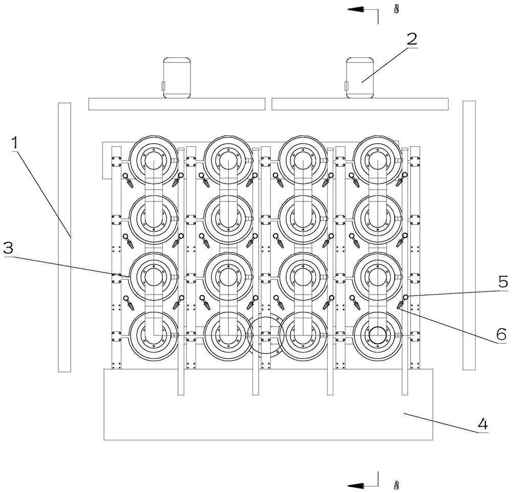
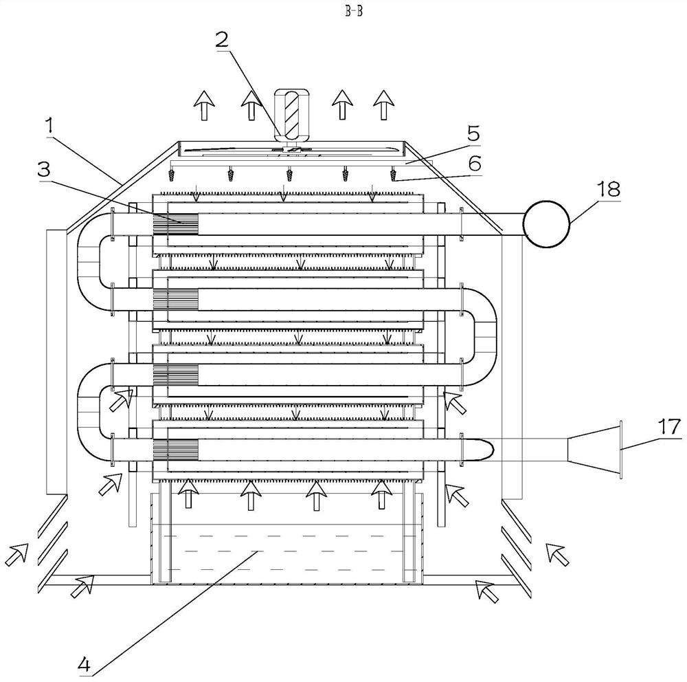
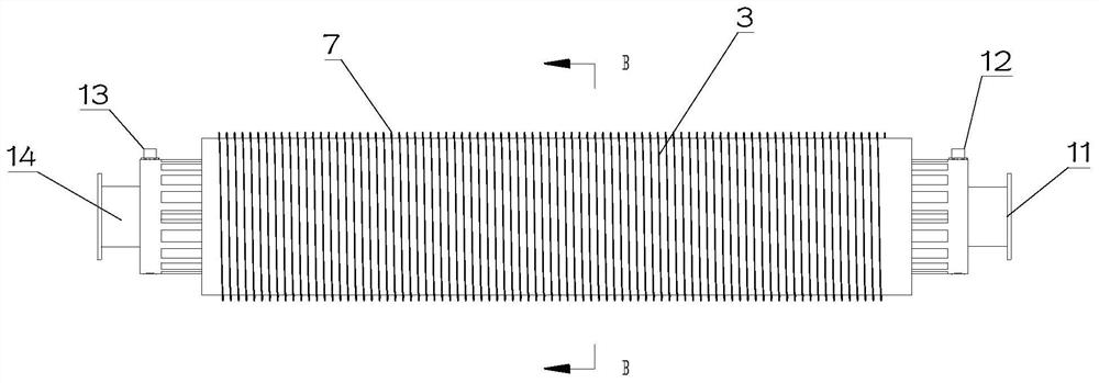
[0031] Such as Figure 1-2 As shown, it is a structural diagram of a flue gas rapid cooling device provided by an embodiment of the present invention, including: a casing 1, a heat exchange component arranged inside the casing 1, the heat exchange component includes a plurality of cooling modules 3, and a plurality of The root cooling module 3 is provided with channels for mutual heat exchange;

[0032] A convection fan 2 arranged at the upper opening of the ...


PUM


Abstract

The invention is suitable for the technical field of incineration, and provides a quick cooling device for smoke. The quick cooling device for smoke comprises a shell, a heat exchange component arranged in the shell, a convection fan arranged on an upper opening of the shell and a sprinkling system, wherein the heat exchange component comprises a plurality of cooling modules, and channels which mutually carry out heat exchange are arranged in the cooling modules; the convection fan is used for enabling air to quickly enter the shell; and the sprinkling system is fixedly in the shell for sprinkling cooling water to the plurality of cooling modules. By use of the quick cooling device, triple heat exchange is realized, and heat exchange efficiency is improved.

Description

technical field [0001] The invention relates to the technical field of incineration, in particular to a flue gas rapid cooling device. Background technique [0002] Existing heat exchangers include shell-and-tube heat exchangers and wall-plate heat exchangers, but they are bulky and inconvenient to clean and maintain. In particular, since the principles of the above heat exchangers are similar, they are generally suitable for relatively pure heat exchange occasions. [0003] If you want to achieve a more efficient heat exchange effect, you need to increase the heat exchange area of ​​the above heat exchanger, which will result in a huge volume and increase the amount of steel used. As the heat exchange area increases, its own resistance to gas and heat exchange liquid will also increase (increasing the heat exchange area means increasing the channel length of its internal runoff, and the diameter of the pipe itself will not increase too much, because if the pipe If the dia...

Claims


Application Information

Patent Timeline
Patent Type & Authority Applications(China)
IPC IPC(8): F23G5/00F23G5/44F23G5/46F23G5/50F23J15/06
CPCF23G5/00F23G5/44F23G5/46F23G5/50F23J15/06Y02E20/30
Inventor 张蕊袁真真
Owner 陕西茵泰科环境工程有限公司
Why Eureka
Try Eureka