Acoustic wave sensor based on Kerr effect

A technology of acoustic wave sensor and Kerr effect, which is applied in the direction of measuring ultrasonic/sonic/infrasonic waves, instruments, utilizing wave/particle radiation, etc. It can solve the problems of low sensitivity of acoustic wave detection methods and achieve good application prospects

Inactive Publication Date: 2020-11-24
中山科立特光电科技有限公司
View PDF0 Cites 0 Cited by
  • Summary
  • Abstract
  • Description
  • Claims
  • Application Information

AI Technical Summary

Problems solved by technology

Conventional sonic detec...

Method used


Image

  • Acoustic wave sensor based on Kerr effect
  • Acoustic wave sensor based on Kerr effect
  • Acoustic wave sensor based on Kerr effect

Examples


Embodiment 1

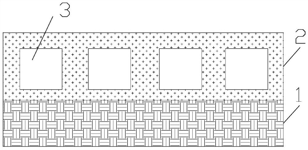
[0021] The invention provides an acoustic wave sensor based on the Kerr effect. Such as figure 1 As shown, the acoustic wave sensor based on the Kerr effect includes a substrate 1 , a piezoelectric material layer 2 and a cavity 3 . The piezoelectric material layer 2 is placed on the substrate 1 , and the surface of the piezoelectric material layer 2 is flat so as to reflect incident light. The material of the base 1 is non-magnetic material. Preferably, the material of the substrate 1 is silicon dioxide. The piezomagnetic material layer 2 can be a metal piezomagnetic material, a ferrite piezomagnetic material, or a rare earth piezomagnetic material. Preferably, the piezomagnetic material layer 2 is a metallic piezomagnetic material, because the metallic piezomagnetic material has high saturation magnetization and excellent mechanical properties, and is convenient for use under high power. The metal piezomagnetic material can be Fe-Co-V system, Fe-Ni system, Fe-Al system, N...

Embodiment 2

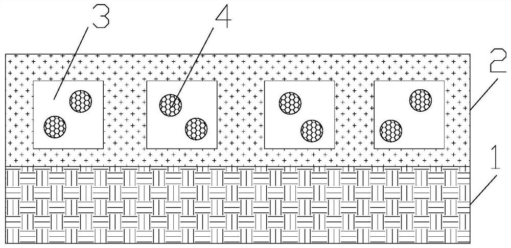
[0028] On the basis of Example 1, such as figure 2 As shown, the cavity 3 is provided with noble metal particles 4 . The material of the noble metal particles 4 is gold. The noble metal particles 4 are spherical. The diameter of the noble metal particle 4 is greater than 20 nanometers and less than 80 nanometers, so as to absorb visible light. The noble metal particle 4 absorbs the incident light, and the incident light excites the noble metal particle 4 to generate surface plasmon resonance, forming a stronger electric field in the piezoelectric material layer 2, thereby enhancing the effect of the incident light on the piezoelectric material layer 2, and improving the Kerr The intensity of the effect increases the sensitivity of acoustic wave detection.

[0029] Furthermore, the distance between the top of the cavity 3 and the surface of the piezoelectric material layer 2 is less than 100 nanometers, so as to enhance the coupling between the incident light and the noble ...

Embodiment 3

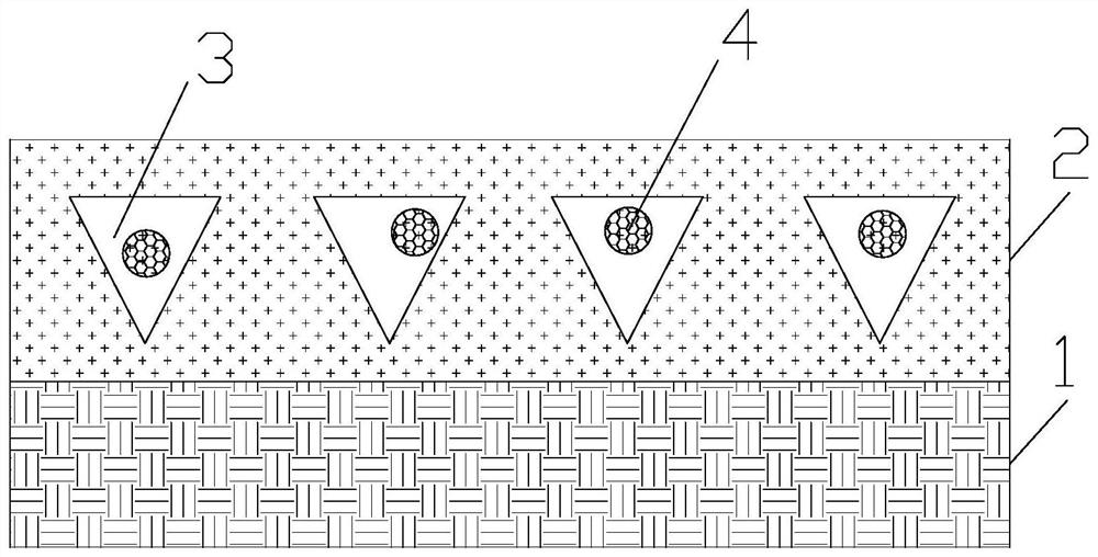
[0031] On the basis of Example 2, such as image 3 As shown, the cavity 3 is an inverted triangle, and the base of the triangle is parallel to the surface of the piezoelectric material layer 2 . Furthermore, the cavity 3 is an inverted isosceles triangle. In this way, the two legs of the isosceles triangle reflect and converge the sound waves, forming a strong sound wave field at the bottom, which strengthens the effect of the sound waves on the top of the cavity 3 in the piezomagnetic material layer 2, and improves the intensity of the Kerr effect. , to improve the sensitivity of acoustic detection.


PUM

PropertyMeasurementUnit
Diameteraaaaaaaaaa
Angle of incidenceaaaaaaaaaa

Abstract

The invention relates to the field of acoustic wave detection, and particularly provides an acoustic wave sensor based on a Kerr effect. A piezomagnetic material layer is arranged on a substrate, thesurface of the piezomagnetic material layer is a plane, and cavities are periodically arranged in the piezomagnetic material layer. When the acoustic wave sensor is applied, the acoustic wave sensor based on the Kerr effect is placed in a to-be-detected environment or is in contact with a to-be-detected object; under the action of sound waves in a to-be-detected environment or a to-be-detected object and the acousti wave sensor based on the Kerr effect, stress in the piezomagnetic material layer is changed, linearly polarized light obliquely irradiates the piezomagnetic material layer, an external magnetic field is applied in the direction perpendicular to the incident plane, and sound wave detection is achieved by detecting the intensity of reflected light. The magnetic conductivity of the piezomagnetic material layer seriously depends on the internal stress borne by the piezomagnetic material layer, so that high-sensitivity detection of sound waves can be realized, and the piezomagnetic material layer has a good application prospect in the field of sound wave detection.

Description

technical field [0001] The invention relates to the field of acoustic wave sensing, in particular to an acoustic wave sensor based on the Kerr effect. Background technique [0002] Acoustic detection is very important in engineering technology. Commonly used acoustic wave detection methods include transmission method, refraction method and reflection method. Conventional sonic detection methods have low sensitivity. Contents of the invention [0003] In order to solve the above problems, the present invention provides an acoustic wave sensor based on the Kerr effect, comprising a substrate, a piezoelectric material layer, and a cavity, the piezoelectric material layer is placed on the substrate, the surface of the piezoelectric material layer is a plane, and the cavity Periodically arranged in the piezomagnetic material layer; in application, linearly polarized light irradiates the piezomagnetic material layer obliquely, applies an external magnetic field in a direction ...

Claims


Application Information

Patent Timeline
IPC IPC(8): G01H9/00
CPCG01H9/00
Inventor 不公告发明人
Owner 中山科立特光电科技有限公司
Why Eureka
Try Eureka