
Real-time monitoring vacuum instrument

A real-time monitoring and vacuum technology, applied in vacuum gauges using ionization effect, vacuum gauges measuring medium pressure by measuring the change of thermal conductivity of medium, etc. Timeliness, equipment failure detection and other issues, to achieve the effect of reducing manual verification steps, shortening time, and improving timeliness

Active Publication Date: 2020-11-24
TIANJIN UNIV OF SCI & TECH
View PDF17 Cites 2 Cited by
  • Summary
  • Abstract
  • Description
  • Claims
  • Application Information

AI Technical Summary

Problems solved by technology

[0003] On the other hand, the generation process involving high vacuum often has a higher standard of safety guarantee requirements, especially for the stability of the vacuum degree in the generation operation process, it needs to be collected and guided by vacuum instruments, but at present, vacuum instruments lack support for remote control. The high-reliability data transmission mode of transmission and monitoring will cause equipment failures to be discovered and dealt with untimely, which will easily delay the timeliness of accident rescue

Method used


Image

  • Real-time monitoring vacuum instrument
  • Real-time monitoring vacuum instrument
  • Real-time monitoring vacuum instrument

Examples


Embodiment Construction

[0035] In order to understand the content of the present invention more clearly, it will be described in detail with reference to the drawings and embodiments.

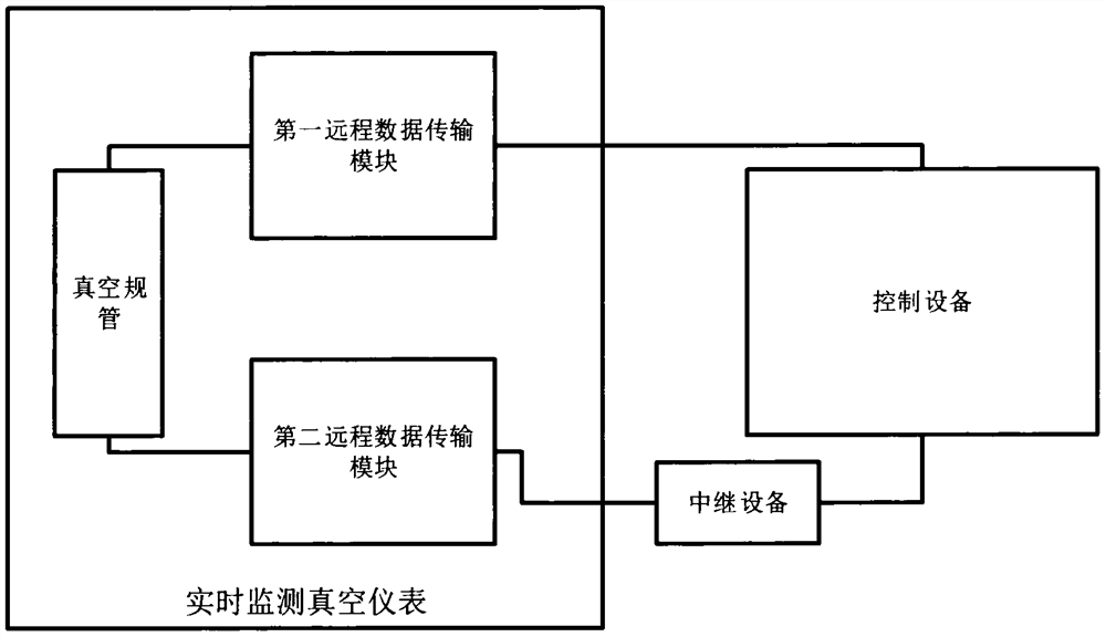
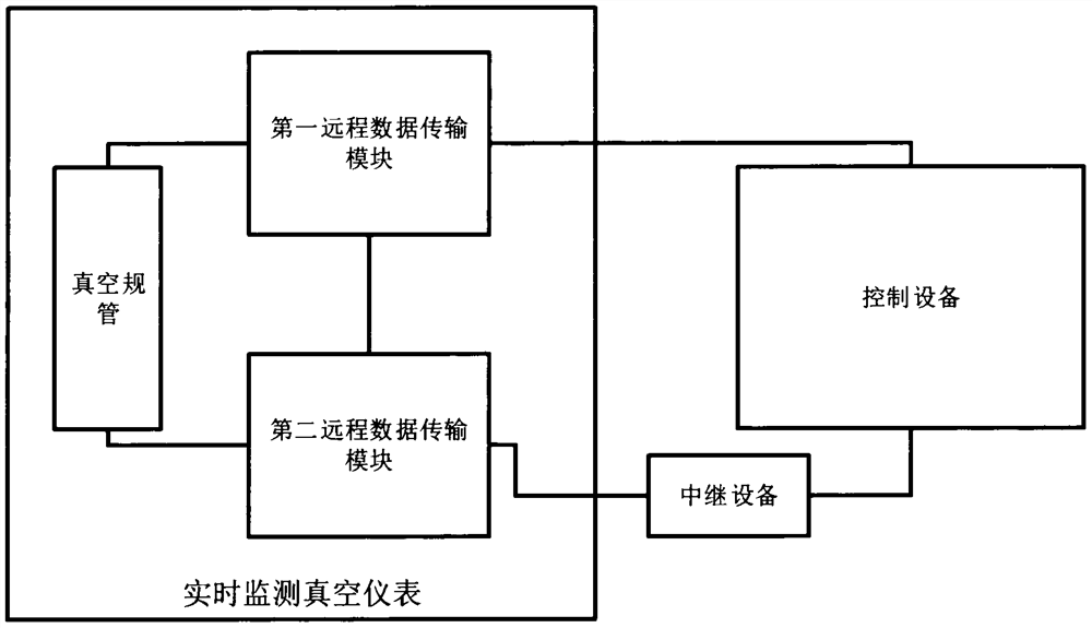
[0036] Such as figure 1 Shown is a schematic structural diagram of the first embodiment of the real-time monitoring vacuum instrument of the present invention, including a vacuum gauge and a first remote data transmission module and a second remote data transmission module respectively connected to the vacuum gauge. The first remote data transmission module and the second remote data transmission module respectively collect and analyze the vacuum measurement values ​​measured by the vacuum gauge by connecting with the vacuum gauge to obtain the first vacuum degree data and the second vacuum degree data respectively. In order to realize mutual verification between different data and ensure the reliability of data transmission, the first remote data transmission module is a wireless network transmission module, and is c...


PUM


Abstract

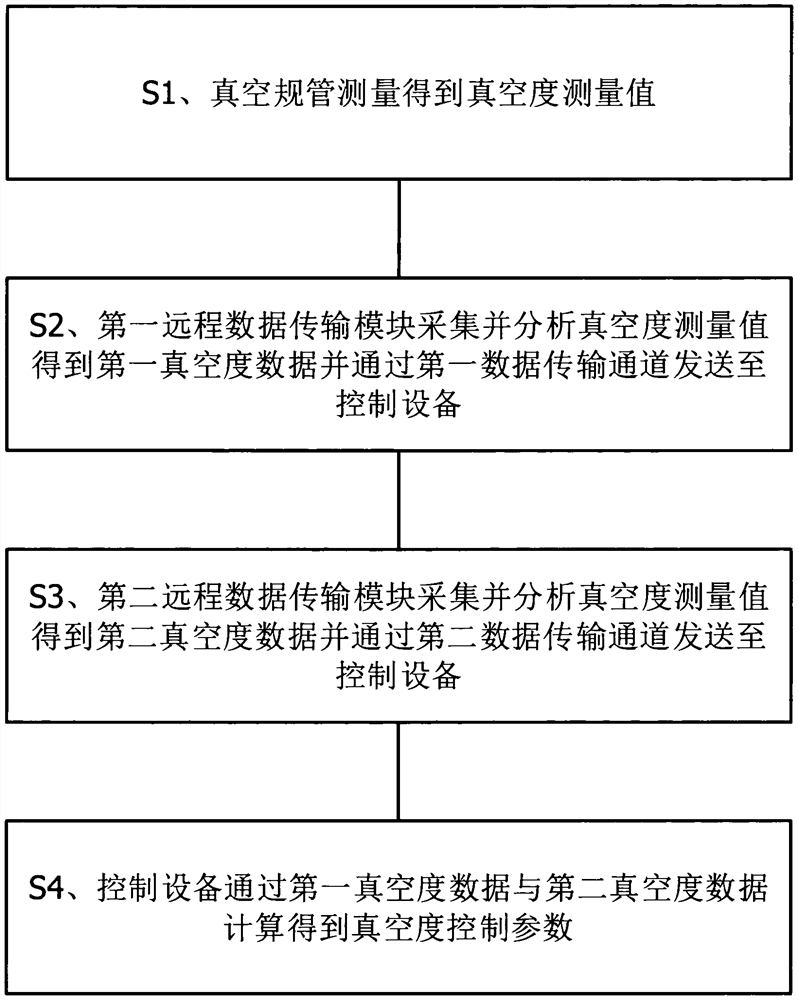
The invention relates to a real-time monitoring vacuum instrument. A real-time and high-reliability feedback transmission channel between the vacuum instrument and control equipment is established through an independent remote data transmission module, so that the equipment fault discovery and processing time is shortened, the timeliness of equipment accident rescue is improved, and the safety ofmonitored high-vacuum equipment can be effectively improved; on the other hand, the invention relates to a vacuum detection control method, the authenticity and effectiveness of the acquired data canbe verified in real time by flexibly comparing the vacuum degree data from different transmission paths, so that the reliability of the vacuum degree monitoring data is ensured, the manual checking steps are reduced, and the equipment operation problem can be found in time.

Description

technical field [0001] The invention relates to the technical field of vacuum degree detection equipment, in particular to a real-time monitoring vacuum instrument. Background technique [0002] Centrifugal Molecular Distillation (Centrifugal Molecular Distillation) is an important form of molecular distillation and a high-tech international liquid-liquid separation or fine separation. The operating condition of centrifugal molecular distillation is generally high vacuum degree, and the low operating pressure can make the distillation temperature far lower than the boiling point of the substance under normal conditions, and there will be no liquid boiling and bubbling behavior, and the residence time of the material to be separated on the evaporation surface It is very short, which can greatly reduce the thermal damage and thermal decomposition of substances, and is currently one of the most ideal distillation methods for separating high-boiling point substances. Among them...

Claims


Application Information

Patent Timeline
Patent Type & Authority Applications(China)
IPC IPC(8): G01L21/12G01L21/34
CPCG01L21/12G01L21/34
Inventor 王红星李飞刘亚男刘洋刘伯潭盖晓龙杨新创王贝贝
Owner TIANJIN UNIV OF SCI & TECH
Learn More